Service Manual
Model No.:
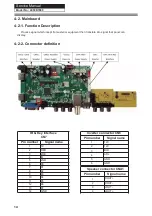
4-2. Mainboard
4-2-1. Function Description
Process signal which incept from exterior equipment then translate into signal that panel can
display.
4-2-2. Connector denition
14
IR & Key Interface
CN7
Pin number
Signal name
1
5V
2
RED
3
GRE
4
IR
5
GND
6
K0
7
K1
8
K2
9
K3
10
K4
11
K5
12
K6
13
K7
14
GND
Inverter connector CN6
Pin number
Signal name
1
12V
2
12V
3
BLO
4
ADJ
5
GND
6
GND
Speaker connector CNA1
Pin number
Signal name
1
ROUT+
2
ROUT-
3
LOUT-
4
LOUT+
LE50B7000
Содержание LE50B7000
Страница 10: ...Service Manual Model No 2 2 External pictures four faces Front Side Up Side 9 LE50B7000 ...
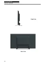
Страница 11: ...Service Manual Model No Right Side Back Side 10 LE50B7000 ...
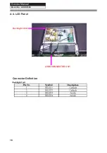
Страница 17: ...Service Manual Model No 4 4 LCD Panel Backlight Unit LVDS CONNECTOR CN1 Connector De nition 16 LE50B7000 ...
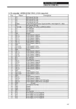
Страница 18: ...Service Manual Model No 17 LE50B7000 ...
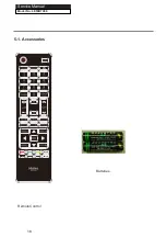
Страница 19: ...P SIZE Batteries RemoteControl 5 1 Accessories Service Manual 18 Model No LE50B7000 ...
Страница 21: ...Service Manual Model No Chapter 6 Operation Instructions 6 1 Front Panel Controls 20 LE50B7000 ...
Страница 30: ...Service Manual Model No 7 2 Wiring Connection Diagram 30 LE50B7000 ...
Страница 36: ...Service Manual Model No 9 2 Mainboard IC Introduction Top view 36 1 2 3 4 5 6 7 8 LE50B7000 ...
Страница 37: ...Service Manual Model No Bottom view 37 LE50B7000 ...

