background image

4-4 Remove the Main board

5HPRYHWKH0DLQERDUG

  Service Manual

  Model No.: 

- 13 -

CN202

CN800

 'LVFRQQHFWHG WKH FRXSOHU

J17

CN201

4-5 Remove the speaker

Take out the speaker

PCN4

Содержание LE32K5000

Страница 1: ...or cautions to advise non technical individuals of potential dangers in attempting to service a product Products powered by electricity should be serviced or repaired only by experienced professional...

Страница 2: ...assemble and Assemble 4 1 Remove the Pedestal 6 8 8 8 8 10 12 12 4 2 Remove the Back Cover 12 4 3 Remove the Adhesive Tape 12 4 4 Remove the Main Board 13 4 5 Remove the Speaker 13 4 6 Remove the Remo...

Страница 3: ...e shooting 54 9 1 Simple Check 54 9 2 Main Board Failure Check 9 3 Panel Failure 55 63 8 1 How to enter into the factory model 8 2 How to update software 51 52 8 Measurements and Adjustments 42 8 3 Ho...

Страница 4: ...instructions in the literture accompanying the appliance 1 3 2 Be careful to the electrical shock 7R SUHYHQW GDPDJH ZKLFK PLJKW UHVXOW LQ HOHFWULF VKRFN RU UH GR QRW H SRVH WKLV 79 VHW to rain or exce...

Страница 5: ...UHFHLYHU RQO WKH WHVW WXUHV VSHFL HG LQ WKLV VHUYLFH PDQXDO CAUTION R QRW FRQQHFW WKH WHVW WXUH JURXQG VWUDS WR DQ KHDW VLQN LQ WKLV UHFeiver 3 Do not spray chemicals on or near this receiver or any...

Страница 6: ...static electricity Such components commonly are called Electrostatically Sensitive ES Devices Examples of typical ES devices are integrated circuits and some field effect transistors and semiconducto...

Страница 7: ...bed in the table below Note A note provides information that is not indispensable but may nevertheless be valuable to the reader such as tips and tricks Caution A caution is used when there is danger...

Страница 8: ...Display 16 7M No of Preset Channels OSD Language English Color System PAL SECAM Audio System DK BG I M L L Audio Output Power Built in W 8W 2 Audio Output Power outer W No Total Power Input W 45W Vol...

Страница 9: ...08 Service Manual Model No 3 Location of Controls and Components 3 1 Board Location No Description A Board Integration Mainboard 3 2 Main Board A Board...

Страница 10: ...el can display RQQHFWRU GH QLWLRQ Main board connector Keypad andremote connector CON4 Pin number Signal name Description 1 LED_R LAMP RED 2 LED_G LAMP GREEN 3 4 IR REMOTE CONTROL 5 GND GND 6 5V POWER...

Страница 11: ...3 3 LED Panel 10 Service Manual Model No LSC320AN02...

Страница 12: ...CLK_N LVDS Clock 7 GND Ground 22 R1CLK_P LVDS Clock 8 GND Ground 23 GND Ground 9 LVDS SEL LVDS Option 24 R1D_N LVDS Signal 10 NC NOTE1 25 R1D_P LVDS Signal 11 GND Ground 26 GND Ground 12 R1A_N LVDS Si...

Страница 13: ...WKDW UHDU FRYHU faces upward 5HPRYH WKH VFUHZ IURP WKH UHDU FRYHU LQGLFDWHG ZLWK 7KHQ UHPRYH WKH SHGHVWDO 4 2Remove the Back Cover 5HPRYH WKHVH VFUHZ LQGLFDWHG RQ JXUH DERYH E 7KHQ UHPRYH WKH EDFN FR...

Страница 14: ...4 4 Remove the Main board 5HPRYH WKH 0DLQ ERDUG Service Manual Model No 13 CN202 CN800 LVFRQQHFWHG WKH FRXSOHU J17 CN201 4 5 Remove the speaker Take out the speaker PCN4...

Страница 15: ...4 6 Remove the remote control take out the remote controlboard Service Manual Model No 14...

Страница 16: ...5 Installation Instructions 5 1 External Equipment Connections Accessories Remote Control User GUIDE Battery Service Manual Model No 15...

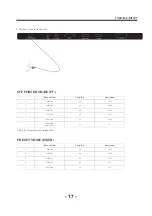
Страница 17: ...cable 2 Connect power cord 3 Power on the TV switch to PC mode 4 Power on the PC This sequence is very important PC Note Aerial connections IEC female Input impendance 75 unbalanced The TV appearance...

Страница 18: ...q Hz not more than 60Hz 1 2 3 640 480 800 600 60 60 31 47 37 88 RESOLUTION V Freq Hz H Freq KHz 1024 768 60 48 36 PRESET MODE HDMI 1 2 3 800 600 1024 768 60 60 37 88 48 36 RESOLUTION V Freq Hz H Freq...

Страница 19: ...O VGA HDMI2 ARC HDMI3 SCART LAN RF HDMI1 YPbPr AV IN HEADPHONE COMMON INTERFACE CI USB USB OPTICAL CVBS DVD Player or other machine with YPbPr YCbCr G R B Audio Video machine with HDMI interfaces R Y...

Страница 20: ...menu When the source device DVD player or Set Top Box supports DVI How To Connect 1 Connect the source device to HDMI port of this TV with a HDMI to DVI cable not supplied with this product 2 A separa...

Страница 21: ...Cable sample HDMI Cable not supplied with the product HDMI to DVI Cable not supplied with the product Analog Audio Cable Stereo to RCA type not supplied with the product Service Manual Model No 20...

Страница 22: ...Use the attached power cord only I WKH SRODUL HG FRUG GRHV QRW W LQWR D QRQ SRODUL HG RXWOHW GR QRW DWWHPSW WR OH RU FXW WKH EODGH W LV WKH XVHUCV UHVSRQVLELOLW WR KDYH DQ electrician replace the obs...

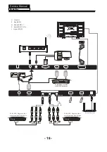
Страница 23: ...put 3 VGA input 4 input 5 input 10 HEADPHONE input 11 AV IN analogue audio output 12 LAN input 13 14 input 15 Output HDMI2 ARC 6 input HDMI3 YPbPr COMMON INTERFACE CI USB OPTICAL 3 1 7 8 9 10 11 15 4...

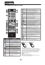
Страница 24: ...ss to display the channel information In teletext mode press to revealthe hidden information Press to open the channel list In teletext mode press to switch the image to top bottom or full These model...

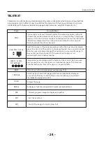
Страница 25: ...ically displayed successively This key is used to stop or resume sub page acquisition The indication appears top left To freeze the page To display or hide the concealed information games solutions Th...

Страница 26: ...71 5V_Normal 950mA STB_EN 12V 1 38A RT9108N AMS1117 3 3V 3 3V_STBY 320MA 3 3V_Normal 150MA AMS1117 3 3V 5V_Normal 150mA AMS1117 3 3V 3 3V_TU 300MA 5V_Normal 300mA FUSE 5V_USB 1A 5V_USB 1A 1 5V_DDR 500...

Страница 27: ......

Страница 28: ......

Страница 29: ...DQSUB B DDR3 DQU7 B DDR3 DQU1 B DDR3 DQL5 AGND GND AVDD_DDR0 AVDD_DDR0 AVDD_DDR0 AVDD_DDR0 1 5V_DDR GND 2 3 4 5 6 7 8 9 10 11 12 13 14 15 16 GND 2 3 4 5 6 7 8 9 10 11 12 13 14 15 16 C317 0 1uF 16V Y5...

Страница 30: ...ND LVB2N LVA2P LVB1N AGND GND GND LVB0P LVB1P LVB2P LVBCLKP LVB3P LVB4P GND LVA0P LVA1P LVA2P LVACLKP LVA3P LVA4P GND GND V_Panel V_Panel V_Panel GND LVB0N LVB1N LVB2N LVBCLKN LVB3N LVB4N GND LVA0N LV...

Страница 31: ......

Страница 32: ...D824 ESD_0402_10pF 1 2 R615 12K R612 10K D820 ESD_0402_10pF 1 2 R613 10K R153 0R NC R6811 75R D811 ESD_0402_10pF 1 2 R619 75R R614 12K R626 10K D819 ESD_0402_10pF 1 2 D821 ESD_0402_10pF 1 2 R611 10K...

Страница 33: ...RIN 3 GND 2 3 4 5 6 7 9 10 11 12 13 14 15 16 R706 10K R703 75R R702 75R R701 75R R705 100R R1411 12K R L P4 PHONE_JACK G_EARPHONE5 A 3 5 2 4 1 R1409 10K D838 ESD_0402_10pF 1 2 R704 100R D842 ESD_0402_...

Страница 34: ...X5R C803 0 1uF 16V Y5V Y3 12MHz D803 NC 1pF DM8 NS EZJZ0V800AA 1 2 DM11 NS EZJZ0V800AA 1 2 C1559 10uF 10V X5R DM9 NS EZJZ0V800AA 1 2 D804 NC 1pF P803 USB W VBUS 4 D 3 D 2 GND 1 SHELL 5 SHELL 6 C1556 0...

Страница 35: ...4 R1463 10K NC R290 1K C0402 330uF 25V C296 RT9108NB TSSOP 28EP_0 65 N16 SD 1 FAULT 2 LINP 3 LINN 4 GAIN0 5 GAIN1 6 AVCC 7 AGND 8 GVDD 9 PLIMIT 10 RINN 11 RINP 12 NC 13 PBTL 14 PVCCR 15 PVCCR 16 BSPR...

Страница 36: ...RF_JACK PAL RF 2 GND 1 GND 3 GND 4 GND 5 C1021 10uF 10V X5R R1010 0R R1005 100R C1048 0 1uF 16V Y5V C1032 150pF C1031 100pF C1022 0 1uF 16V Y5V L1005 330nH SDWL1608CR33JSTFM01 C1034 1uF 16V Y5V D201 B...

Страница 37: ...0 3 13 PCM_A1 3 13 PCM_A2 3 13 PCM_A3 3 13 PCM_A4 3 13 PCM_A5 3 13 PCM_A6 3 13 PCM_A7 3 13 GND 2 3 4 5 6 7 8 9 10 11 13 14 15 16 C1205 0 1uF 16V Y5V NC C1208 NC 33pF C1207 NC 33pF C1204 0 1uF 16V Y5V...

Страница 38: ...V_Normal 5V_PCMCIA TS1_SYNC 3 PCM_IOWR_N 3 PCM_CE_N 3 TS1_VLD 3 TS1_CLK 3 PCM_WAIT_N 3 PCM_RESET 3 PCM_A 14 0 3 12 TS0_CLK 3 PCM_REG_N 3 PCM_D 7 0 3 PCM_IRQA_N 3 PCM_WE_N 3 PCM_OE_N 3 PCM_CD_N 3 TS0_V...

Страница 39: ...01 0 1uF 16V Y5V CB1401 1000pF 2KV NC Green Yellow P1401 RJ45 W TD 1 TD 2 RD 3 TDCT 4 RDCT 5 RD 6 NC 7 CH_GND 8 GRN 9 GRN 10 ORG 12 ORG 11 GND1 13 GND2 14 R1404 75R 1 R1401 75R 1 CB1402 1000pF 2KV U14...

Страница 40: ...N 5 GND 1 VIN 3 FB OUT 4 SW 2 BST 6 RP5 10K R1499 3K_1 C1476 10uF 10V X5R C40 10uF 25V X5R RP17 10K C1499 10uF 25V X5R R1496 7 5K_1 Q504 MEM2303M3G 1 2 3 CP21 0 1uF 16V Y5V R1494 39K_1 RP18 10K C1493...

Страница 41: ...PR63 PR76 PFU1 T3 15AL 250AC PR29 PR80 PR61 PR67 PR12 PC15 PD8 PC23 PR43 PR51 PR84 PC6 PCX1 PC29 PCX2 PR85 PC16 PC12 PC7 PR19 68R 1206 PC42 PR32 PR9 PD14 RS1M PR14 PR35 PCY1 PC62 PR49 PD5 PR31 PD3 PL9...

Страница 42: ...ght Service Manual Model No 7 3 Wiring Connection Diagram NO Name 1 2 3 4 5 Connection Wire For Keyboard and Remote Connection Wire For Speaker LVDS Wire Connection Wire Power Wire 5 2 3 4 1 41 6 6 Co...

Страница 43: ...t the Cancel button then press the OK button to go back the previous menu 2 Press the buttons to select DVB T DVB C and then press the OK button to confirm Press the Menu button to back to the previou...

Страница 44: ...der the current mode General Step for Menu Setup For each main menu first press button to enter the submenu Press buttons to select the desired adjustable option After the selection of option is compl...

Страница 45: ...s to select the Full Tuning or Quick Tuning In the other operator press and OK buttons to select the Full Tuning or Network Tuning SCENE ENERGY TUNER SYSTEM Auto Tuning SCALE Antenna Type Manual Tunin...

Страница 46: ...l and the press the OK button to commence the search of that channel When the signal has been tuned the picture and signal strength will be display on the screen 4 Press the MENU button to return back...

Страница 47: ...m Advanced Option and then press OK to confirm 5 1 Language 1 Press the buttons to select the Language menu then press the OK button to enter the language submenu 2 Press buttons select the OSD langua...

Страница 48: ...on Press the button to enter the home network menu press the buttons to select the device then press OK button to confirm Press the buttons to select the desired option in the file list then press the...

Страница 49: ...channel in the day To access the EPG menu press the GUIDE button the following menu will be displayed to enter the PROGRAMME GUIDE PROGRAMME GUIDE 19 Nov 2004 16 00 16 30 SD Multiple Audio The show w...

Страница 50: ...SB storage device and to resume to the point where it was paused Note Formatting a USB2 0 storage device will be needed Save your original data before formatting All the data stored in the USB device...

Страница 51: ...Return Exit usb sda1 LOST DIR Tencent _MSTPVR MIDE_0 9 1 USB1 Movie Photo Music 00 00 40 00 02 24 90 Pause 1 big big world 2 Just One Last big big world mp3 00 00 39 00 03 26 Pause Since then all of...

Страница 52: ...is on Off the unit will stand by when the AC switch is on Last when the AC switch is on the unit will be the same as the last time 6 Other 6 1 PICTURE MODE change the parameters of contrast brightnes...

Страница 53: ...update You should reset TV after update Note When Upgrade on the process please don t Power Off Haier 6308N upgrade with USB SOP Step 1 Ready for F W Upgrade 1 1 Prepare a USB memory RS WKH VRIWZDUH O...

Страница 54: ...ource Lock is on you can choose 7 Panel key Lock set keypad locked or not 8 OSD Lock Set OSD menu display or not when press menu key 9 Standby LED Power Set Indicating lamp display or not 10 USB Cloni...

Страница 55: ...Service Manual Model No 9 Trouble shooting 9 1 Simple check 54...

Страница 56: ...Service Manual Model No 9 2 Main board failure check 55...

Страница 57: ...having problems Check if there is sound input signal Check the P8 JACK Yes No Check if there is signal at L201 and L202 Check if there is signal at C222and C223 No Yes Check HEADPHONE have sound Chec...

Страница 58: ...J19 ON OFF High Remote ON No Yes Check CE39 5VSB Change U1403 No Yes Check U104 3 3Vsb Change U104 U201 No Yes Check C512 1 18V CE38 1 5V Change U109 U501 U201 No Yes Check Y201 24MHz Change Y201 No Y...

Страница 59: ...put No Update the software and make the reboot Still having problems For ease of use recommend that customer format the picture and sound settings in the automatic option Yes Change L L16 L25 L18 L19...

Страница 60: ...fer to relative instructions in the Manual for color adjust No No Yes Yes Check out of picture and sound system of this channel Change the channel to the right sound system PAL D K No color for some c...

Страница 61: ...adj to high then check blacklight is shine How to know whether the Power Module is broken Still having problems Check if Main board LVDS wire Panel are in good condition No Power Module is broken Yes...

Страница 62: ...Power Module not work 61...

Страница 63: ...p MSD6308RTEM DDR AudioAMP 4 Verify if the FLASH U1202 has the right software and work well 5 Verify if the Y201 Crystal has the right frequency Panel not work 1 output and input are working 2 Verify...

Страница 64: ...r cracking Dim or L D TCP Sunken TCP lead cracking ACF bonding short Awful environment and something electric enter into LCD Mis align between TCP and Panel Panel failure TCP failure V Dim Vertal gray...

Страница 65: ...r Bubble Bladder in Polarizer Bladder between Polarizer and top glass Polarizer Scratch Polarizer Scratch Tine or rigidity arose F M i n s i d e Polarizer Eyewinker inside Polarizer Eyewinker inside P...
Страница 66: ...isplay Maybe caused by surge current and EDS Black Screen B L normal only Black screen display FIIcker Crosstalk LCD Vcom imbalance Abnormal Color Only color abormal Capacitance improper bring crossta...

Страница 67: ...s between wire and electrode B L dark B L brightness darker than normal Connect badnessShort between wire and electrode B L wire damaged B L wire damaged Operation abnormal or systemic noise B L wire...

Страница 68: ...iption Phenomena Failure cause Mechanlcal or B L Light leakage Brightness at bottom of LCM brighter than normal B L unit badness Uniformity B L brightness asymmetric Sheet in B L unit is uneven Mount...

Отзывы: