- 27 -
5
5
4
4
3
3
2
2
1
1
D
D
C
C
B
B
A
A
T_SDA
IF_AGC
AIF
IF-
IF+
T_SCL
T_RF_AGC
RF_AGC
T_RF_AGC
S
VIFP_OUT
IFAGC
RF_AGC
VIFN_OUT
SIFP_OUT-
T_SDA
3.3VCC_T
T_SCL
3.3VCC_TM
IFAGC
T_RF_AGC
SSDA
SSCL
IFAGC
AIF
IFS1
IFS2
S
IF+
IF-
VIFN_OUT
VIFP_OUT
SIFP_OUT-
IFS1
IFS2
RF_AGC_SEL
VIFN_OUT
VIFP_OUT
IF-5V
5V-Tuner
IF-5V
+5V
+3.3V_SB
3.3VCC_T
Vdd_A1.6V_D
+5V
3.3VCC_T
3.3VCC_T
3.3VCC_T
3.3VCC_T
Vdd_A1.6V_D
3.3VCC_T
3.3VCC_T
1.8VCC
3.3VCC_T
Vdd_A1.6V_D
1.8VCC
Vdd_A1.6V
Vdd_A1.6V
Vdd_A1.6V_D
+8V
5V-Tuner
+12V
+5V_LDO
5V-Tuner
AGND
+8V
+5V
+5V
1.8VCC
+1.8V
IF+
4
IF-
4
TUNER_I2C_SCL
4
TUNER_I2C_SDA
4
DEMOD_IF_AGC
4
VIF_P
4
VIF_M
4
SIF_IN-
4
4
RF_AGC_SEL
4
D_RF_AGC
4
RF AGC Switch
Closed to MstIC
RF Input
Port
Vdd_RF_VCO_LO_3V
Put on digital GND plane
301RF V7 MM 301RF V8 302RF V8
Pin 1 R23 0 DNP DNP
Pin 1 R24 DNP 0 0
75 ohm Line
LNA GND
Important:
Analog GND and digital GND is still separate,
but through Paddle GND connecting them,
please talk to SYU if anything not understood
Vdd_IO
Close Silicon Tuner
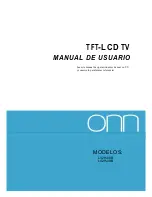
DESIGN:George Guo
MODEL: MSAV3207-K3
TITLE: TUNER
CHECKED:
Date: Feb. 3,2010
APPRD:
SHEET: 8 OF 9
VER:1.0
5.19V 116mA (ATV)
Vpp
80mv
Vpp
80mv
For silicon tuner
If use single saw filter(internal),
Delete R276,R280
Add R283(0R)
Delete Q59
Delete C73
If use single saw filter(internal),
Delete these parts of this area
CS30
10nF
CS30
10nF
CS24
18PF
CS24
18PF
U12
AMS1084CD-ADJ
U12
AMS1084CD-ADJ
VIN
3
VOUT
2
ADJ
1
TAB
4
R139
NC/680R
R139
NC/680R
CS39
100uF/16V
CS39
100uF/16V
RS26
1K
RS26
1K
CS1
0.1uF
CS1
0.1uF
RS21
1K
RS21
1K
LS12
120ohm_FB
LS12
120ohm_FB
R276
1K
R276
1K
RS4
391R
RS4
391R
CS22
0.1uF
CS22
0.1uF
CS27
NC
CS27
NC
RS8
1M
RS8
1M
R288
0R
R288
0R
+
EC6
470uF/16V
+
EC6
470uF/16V
CS18
82pF
CS18
82pF
R141
NC/4.7K
R141
NC/4.7K
LS6
120ohm_FB
LS6
120ohm_FB
LS4
33nH
LS4
33nH
CS32
0.1uF
CS32
0.1uF
RS17
100R
RS17
100R
SAW
U23
M3953M
SAW
U23
M3953M
ING
2
OUT1
4
GND
3
OUT2
5
IN
1
CS17
0.1uF
CS17
0.1uF
C222
0.1uF
C222
0.1uF
CS34
10nF
CS34
10nF
CS6
10nF
CS6
10nF
LS15
120ohm_FB
LS15
120ohm_FB
CS3
0.1uF
CS3
0.1uF
C559
0.1uF
C559
0.1uF
C8
0.1uF
C8
0.1uF
CS4
1nF
CS4
1nF
C73
10nF
C73
10nF
DS1
BAV99
DS1
BAV99
3
1
2
R279
10K
R279
10K
R532
47R
R532
47R
B1
GND
B0
A
S
VCC
U28
FSA3157P6X
B1
GND
B0
A
S
VCC
U28
FSA3157P6X
1
2
3
4
5
6
RS16
100R
RS16
100R
CS35
10nF
CS35
10nF
C143
0.1uF
C143
0.1uF
FB5
FB56R/1A
FB5
FB56R/1A
CS9
0.1uF
CS9
0.1uF
Y2
24.000MHZ
Y2
24.000MHZ
1
2
L7
NC/1uH
L7
NC/1uH
R437
10K
R437
10K
J1J1
RS20
100R
RS20
100R
CS14
27pF
CS14
27pF
RS10
NC
RS10
NC
C139
22nF
C139
22nF
+
EC16
470uF/16V
+
EC16
470uF/16V
RS15
4.7K
RS15
4.7K
R156
820R
R156
820R
LS11
220nH
LS11
220nH
LS16
220nH
LS16
220nH
C71
NC/10uF
C71
NC/10uF
RS25
0R
RS25
0R
B1
GND
B0
A
S
VCC
U29
FSA3157P6X
B1
GND
B0
A
S
VCC
U29
FSA3157P6X
1
2
3
4
5
6
R438
10K
R438
10K
RS3
10K
RS3
10K
CS20
2.2uF
CS20
2.2uF
ADJ
OUT
IN
US2
AMS1117-ADJ
ADJ
OUT
IN
US2
AMS1117-ADJ
3
2
1
4
R153
150R
R153
150R
CS28
100uF/16V
CS28
100uF/16V
LS10
120ohm_FB
LS10
120ohm_FB
CS31
39pF
CS31
39pF
CS8
4700pF
CS8
4700pF
R216
100R
R216
100R
L3
NC/2.2uH
L3
NC/2.2uH
CS10
56pF
CS10
56pF
F Conn
JS1
F Conn
JS1
1
3
4
2
5
6
7
8
9
10
C20
0.1uF
C20
0.1uF
RS14
4.7K
RS14
4.7K
Q58
3904
Q58
3904
J21J21
C84
0.1uF
C84
0.1uF
CS29
0.1uF
CS29
0.1uF
R217
100R
R217
100R
C72
NC/15nF
C72
NC/15nF
U24
DA58GT-13-E
U24
DA58GT-13-E
NC
1
+5V
2
RF-AGC
3
BT
4
AS
5
SCL
6
SDA
7
B2
8
IF-AGC
9
DIF2
10
DIF1
11
AIF
12
GND
13
GND
14
GND
15
GND
16
J13J13
R278
10K
R278
10K
RS13
0R
RS13
0R
LS7
330nH
LS7
330nH
RS1
NC/1K
RS1
NC/1K
CS36
0.1uF
CS36
0.1uF
C221
0.1uF
C221
0.1uF
U13
AMS1084CD-ADJ
U13
AMS1084CD-ADJ
VIN
3
VOUT
2
ADJ
1
TAB
4
CS23
18PF
CS23
18PF
C262
4700pF
C262
4700pF
CS26
2.2uF
CS26
2.2uF
RS7
NC
RS7
NC
LS8
12nH
LS8
12nH
R280
10K
R280
10K
LS5
120nH
LS5
120nH
R533
47R
R533
47R
RS24
NC
RS24
NC
C150
20pF
C150
20pF
C82
10uF
C82
10uF
R150
NC/22R
R150
NC/22R
R137
NC/56R
R137
NC/56R
RS23
NC
RS23
NC
CS5
0.1uF
CS5
0.1uF
CS33
10nF
CS33
10nF
C142
22nF
C142
22nF
R157
680R
R157
680R
CS2
2.2uF
CS2
2.2uF
C149
20pF
C149
20pF
LS3
3.6nH
LS3
3.6nH
C263
4700pF
C263
4700pF
ADJ
OUT
IN
US1
AMS1117-3.3
ADJ
OUT
IN
US1
AMS1117-3.3
3
2
1
4
Q59
3906
Q59
3906
R151
0R
R151
0R
R138
NC/100R
R138
NC/100R
F1
U4
MXL302RF_V8_F1_32
F1
U4
MXL302RF_V8_F1_32
LNA_IN
2
AS
6
IDAC
3
VDD_DNX2
1
VBATT_A3
4
VAGC2
5
VBATT_A5
7
XTAL_N
8
XTAL_
P
9
CLK_
OUT
10
GND_
XTAL
11
VREG_
A_
OUT1
12
VDD_DNX1
31
TF_2
30
TF_3
29
VREG_
A_
OUT2
28
VBATT_A2
27
VAGC1
26
IF_OUTP2
23
VBATT_A1
13
SCL
14
SDA
15
IF_O
UTP
25
VDD_IO
16
GND_DIG
17
VREG_D_OUT
18
VREG_D_IN
19
VBATT_A4
20
VDD_REF_SX
21
IF_OUTN2
22
IF_OUTN
24
PADDLE
33
TF_1
32
C214
10nF
C214
10nF
LS9
120ohm_FB
LS9
120ohm_FB
LS2
120ohm_FB
LS2
120ohm_FB
RS27
470R
RS27
470R
LS1
120ohm_FB
LS1
120ohm_FB
R283
NC/0R
R283
NC/0R
RS22
1K
RS22
1K
CS7
4700pF
CS7
4700pF
CS13
39pF
CS13
39pF
R282
NC/1K
R282
NC/1K
LS14
120ohm_FB
LS14
120ohm_FB
C25
0.1uF
C25
0.1uF
C83
0.1uF
C83
0.1uF
R140
NC/1.5K
R140
NC/1.5K
CS12
1nF
CS12
1nF
SAW
U22
M9370M
SAW
U22
M9370M
ING
2
OUT1
4
GND
3
OUT2
5
IN
1
R290
0R
R290
0R
R440
100K
R440
100K
LS13
120ohm_FB
LS13
120ohm_FB
RS19
0R
RS19
0R
+
CS25
100uF/16V
+
CS25
100uF/16V
R154
220R
R154
220R
L4
NC/2.2uH
L4
NC/2.2uH
C74
10uF
C74
10uF
Q12
NC/2SC2216
Q12
NC/2SC2216
3
1
2
RS9
47R
RS9
47R
C220
10nF
C220
10nF
CS19
0.1uF
CS19
0.1uF
R281
10R
R281
10R
CS16
180pF
CS16
180pF
R534
100R
R534
100R
RS5
0R
RS5
0R
RS12
NC
RS12
NC
RS2
391R
RS2
391R
RS18
120R
RS18
120R
RS6
1M
RS6
1M
R271
NC/39R
R271
NC/39R
Содержание L32B1120
Страница 3: ... 02 9 Trouble shooting 43 9 1 Simple Check 43 9 2 Main Board Failure Check 9 3 Panel Failure 44 53 ...
Страница 13: ...3 4 LCD Panel 12 02 9 ...
Страница 18: ... 17 ...
Страница 19: ... 18 ...
Страница 20: ... 19 ...
Страница 24: ...6 Operation Instructions Basal information 6 1 Front panel controls 6 2 Back panel controls 23 ...
Страница 25: ...6 3 Setting Up Your Remote Control 24 ...
Страница 26: ...7 Electrical parts 7 1 Block diagram 25 AMP Headphone Coaxial 1 2 MSD318QT Main IC ...
Страница 37: ...8 TV OPERATION 36 ...
Страница 38: ... 37 ...
Страница 39: ... 38 Press ENTER Key To Select ...
Страница 40: ... 39 Press ENTER Key To Select ...
Страница 41: ... 40 ...
Страница 44: ... 43 9 Trouble shooting 9 1 Simple check ...
Страница 46: ... 45 3 Panel display abnormally connector J9 is at normal level ...
Страница 50: ... 49 7 PC no picture or picture abnormal ...
Страница 51: ... 50 8 YPBPR AV no picture or picture abnormal Check Y ...