18
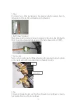
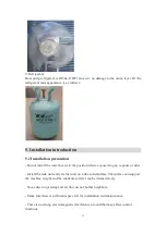
until you hear the coolant leak, and release the pin and close the valve of the the pipe;
b) Keep under control the weight of the refrigerant tank through the electronic scale;
c) Open the ball valve and to flow the refrigerant gradually;
d) After reaching the mass of gas to be loaded close the tap;
e) Remove the manometer and charging hose from the valve;
f) with the detector and check for leaks of refrigerant;
g) Remove the container from the manifold and replace all the plugs (E).
h) Once finished the time for the
Ā
Charge
ā
, verify proper product functioning.
5.9 Installation caution
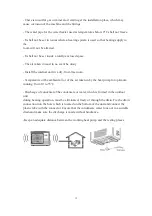
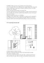
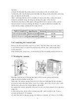
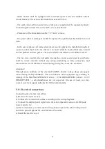
When making the connections, you should respect the standards and local directives.
- Select copper pipes for pipeline connection.
- The inlet water pressure is between 0.1~0.6MPa. If lower than 0.1 MPa, a booster
pump shall be added at the water inlet; if higher than 0.6 MPa, a pressure relief valve
shall be added at the water inlet.
- The inlet water temperature is suggested between 10-30
e
C.
- Outdoor water pipeline and valves should be proper insulated.
- In accordance with safety rules, a safety valve(8.5bar,99
e
C,G3/4M) must be
installed on the tank.For France, we recommend hydraulic safety units fitted with a
membrane with the NF marking.
Integrate the safety valve in the cold water circuit.Install the safety valve close to the
tank in a place which is easy to access.
No isolating devices should be located between the safety valve or unit and the tank.
- Never block the outlet of the safety valve or its drain line for any reason.
- The diameter of the safety unit and its connection must be atleast equal to the
diameter of the domestic cold water inlet.
- If the mains pressure exceeds 80% of safety valve, a pressure reducer must be
installed upstream of the appliance.
Do not connect the cold water inlet and hot water outlet directly to the copper
pipes in order to avoid iron/copper galvanic couples (risk of corrosion).
The cold water inlet and hot water outlet must be fitted with a dielectric connection
(not supplied).
Содержание HP200S1
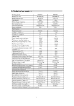
Страница 5: ...5 3 Technical parameters ...
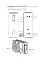
Страница 6: ...6 4 Description of parts and components 4 1 Heat pump structure HP200 300S1 ...
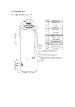
Страница 7: ...7 4 2 Exploded view 4 2 1 Exploded view tank unit ...
Страница 13: ...13 5 2 Installation dimensions mm ...
Страница 21: ...21 ...
Страница 23: ...23 5 13 Wiring diagram ...
Страница 24: ...24 6 Operation and functions Display 6 1 Description of the pictograms ...
Страница 25: ...25 ...
Страница 29: ...29 8 Faults and protection 8 1 Fault type ...
Страница 30: ...30 8 2 Fault code identification method ...
Страница 31: ...31 ...
Страница 32: ...32 ...
Страница 33: ...33 ...
Страница 37: ...37 9 2 Remove the Control panel Use a screwdriver to remove the screws Remove it Remove it ...


