Service Manual
17
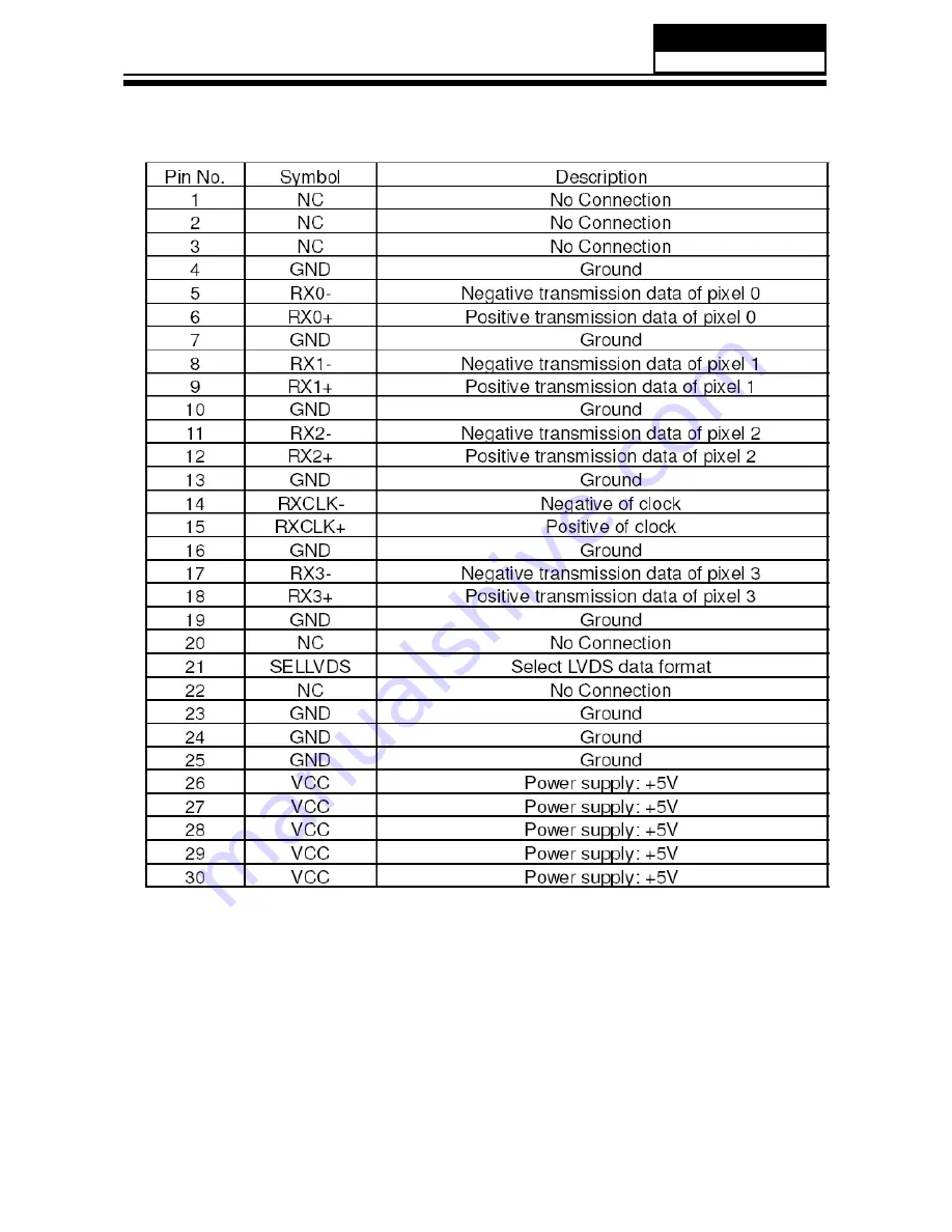
Panle LVDS Connector (CNC4)
Model No.: HLC22XSLW2
Страница 1: ...ct Products powered by electricity should be serviced or repaired only by experienced professional technicians Any attempt to service or repair the product or products dealt with in this service infor...
Страница 2: ...sed in this manual 6 1 4 How to Read this Service Manual 6 1 4 1 Using icons 6 KDSWHU 6SHFL FDWLRQ 6SHFL FDWLRQ OLVW 8 2 2 External pictures four faces 9 Chapter 3 Disassemble and Assemble 11 11 11 12...
Страница 3: ...m 25 7 3 Circuit Diagram 27 7 2 Wiring Connection Diagram Chapter 8 Measurements and Adjustments 8 1 Service Mode 40 8 1 1 How to enter into Service Mode 40 8 1 2 How to exit 40 8 2 Measurements and A...
Страница 4: ...tant thing is to list up the potential hazard or risk for the service personnel to open the units and disassemble the units For example we need to describe properly how to avoid the possibility to get...
Страница 5: ...YLQJ DQ HOHFWULFDO DVVHPEO HTXLSSHG ZLWK 6 GHYLFHV SODFH WKH DVVHPEO RQ D conductive surface such as aluminum foil to prevent electrostatic charge buildup or exposure of the assembly 1 3 4 About lead...
Страница 6: ...th CAUTION 7KLV LV D DPPDEOH PL WXUH 8QOHVV VSHFL HG RWKHUZLVH LQ WKLV VHUYLFH PDQXDO OXEULFDWLRQ RI FRQWDFWV LV QRW UHTXLUHG Capacitors may result in an explosion hazard 5 Do not defeat any plug sock...
Страница 7: ...Minimize bodily motions when handling unpackaged replacement ES devices Otherwise harmless motion such as the brushing together of your clothes fabric or the lifting of your foot IURP D FDUSHWHG RRU...
Страница 8: ...HTXLSPHQW ORRVH GDWD JHW DQ XQH SHFWHG UHVXOW RU KDV WR restart part of a procedure Warning A warning is used when there is danger of personal injury Reference A reference guides the reader to other p...
Страница 9: ...No of Preset Channels 181 OSD Language English French Spanish Color System NTSC Audio System M BG I L L Audio Output Power Built in W 3W 2 YES Total Power Input W 40W Voltage Range V AC100V 240V 3RZHU...
Страница 10: ...Service Manual 9 2 2 External pictures four faces Front Side Left Side Model No HLC22XSLW2...
Страница 11: ...Service Manual Model No HLC22XSLW2 10 Right Side Back Side...
Страница 12: ...Remove the LCD Panel 3 3 Remove the Main Board Service Manual Model No HLC22SLW2 11 Lay down the unit so that rear cover downward Remove the one screw from the pedestal indicated with Then remove the...
Страница 13: ...ntrol Board 3 4 Remove the Speaker 3 5 Remove the Keypad Assembly 3 6 Remove the Remote Control Board Service Manual Model No HLC22SLW2 12 Remove the DVD label indicated with Remove the two screw indi...
Страница 14: ...Chapter 4 Location of Controls and Components 4 1 Board Location 4 2 Main Board Service Manual 13 No Description A Board Main Board B Board C DVD LED Driver Board Model No HLC22XSLW2...
Страница 15: ...ply unit path System board will use this pin to control system power CN1 Pin 4 Control the luminance of backlight The system can generate the PWN signal to control the strength of TFT LCD Panel s back...
Страница 16: ...3 Signal 18 LVDS_D3E_P LVDS EVEN 3 Signal 19 GND Ground 20 NC NC 21 NC NC 22 NC NC 23 GND Ground 24 GND Ground 25 GND Ground 26 Panel_power Power for panel 27 Panel_power Power for panel 28 Panel_pow...
Страница 17: ...CTOR CNC1 Service Manual Model No HLC22XSLW2 16 Power supply and Inverter Connector CNC1 Pin number Signal name Description 1 1 Ground 1 Ground 867 19 57 5 LJKWQHVV GMXVW 21 2 19 57 5 6ZLWFK RQWURO 9...
Страница 18: ...Service Manual 17 Panle LVDS Connector CNC4 Model No HLC22XSLW2...
Страница 19: ...picture quality in a poor signal area please purchase a signal amplifier and install properly If the antenna needs to be split for two TV s install a 2 Way Signal Splitter in the connections To instal...
Страница 20: ...ment B Refer to external equipment operating guide Component Setup How to connect Connect the DVD video outputs COMPONENT to A the Y Pb Pr jacks on the TV and connect the DVD audio outputs to the YPbP...
Страница 21: ...rovider you can watch cable TV programming The TV cannot display TV programming unless a TV tuner device or cable TV converter box is connected to the TV For further information regarding cable TV ser...
Страница 22: ...oduct 2 A separated audio connection is necessary 3 If the source device has an analog audio output connector connect the source device audio output to DVI Audio In port located on the left side of HD...
Страница 23: ...f headphones at a high volume may damage your hearing You will not receive sound from the speakers when you connect headphones to the system Analog Audio Cable Stereo to RCA type not supplied with the...
Страница 24: ...to MP3 songs 4 Digital Out Connect various types of digital audio equipment 5 HDMI In Connect a HDMI device to receive digital audio and uncompressed digital video 6 VIDEO In Connect the video signal...
Страница 25: ...Press to open the on screen menu A Thumbstick Up Down Left Right Allows you to navigate the on screen menus and adjust the system settings to your preference B SLEEP button Press to display the sleep...
Страница 26: ...Electrical Parts 7 1 Block Diagram 25 HDMI1 VGA YPbPr tuner Composite MT5305 Main IC YPbPr Composite L R VGA P11 L R DDR Flash TDA1517 P A N E L USB LVDS EEPROM I2C Bus Service Manual DDR Model No HL...