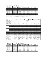
Haier HC18D1VAR Скачать руководство пользователя страница 16

5

PU

ELECTRIC HEATER KIT

RD

BL

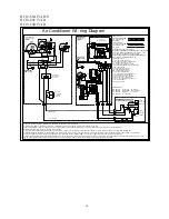
Air Conditioner Wi ri ng Diagram

1) Confi rm sy stem selec tion.  Opti onal com ponents m ay be field or factor y installed.
2) If LPS and/or HPS not in stalled or removed, a ju mper wire must be present acr oss circu it for syst em to operate.
3) For  pr oper  syste m oper ation, consul t indo or  uni t and outdoor  unit  installat ion inst ructi ons to con firm syst em mat ch up and blower spe ed sel ect io n.

4) Alt ernat e double  pole  contac tor us ed on some syst ems.
5) Onl y one sta rt assist method to be u sed at a ti me, consul t outdoo r un it inst all ati on instr ucti ons for  app lication information. Use only f act ory appr oved accesso ries.
6) Opti onal OFM com ponents m ay connect capac itor com mon and mo tor com mon, for r ecipr ocati ng compres sor ther e may have cran kcase heat er co nsu lt ou tdoor u nit inst allat ion
inst ruct ions for d etails.Select the run ning capa cit or(one or  dua l)and connect.If IFM or OFM only  have on e capacit or wire,co nnec t Com wire t o cap aci tor.
7) Indoor  uni t s hipped w ithout optional  electr ic heater  ki t.  To inst all  opt ional heat er ki t,remove po wer pi g tail up to 9 pin plug.  Inst all heater kit and con nect  with mating 9 pin plu g.  Run
syst em power connect ions di rect ly to elect ric h eater kit pow er terminals. Consult heat er ki t inst allation instructions for complete det ails.

RD

24VAC COMMON

COMPRESSOR

BL

YL

208/230V

60Hz 1PH

C

BL

BL

YL

YL

Y

2

YL

P3

P2

P1

6

RD

R

L1

GND

L2

BK

BK

WH

C

S

CC

4

RD

YL

2

1

NC

Opt ion al
Low &  High
Pressur e
Switches

LPS

HPS

Compress or
Prot ect 3 Min.
Time Delay

BCAP

RD-LO

RD

L2

RD

OR

BK- HI

M

IBM

3

GR

PU

L1

BK

BK

R

S

BR

BR

208

COM

BL

R

TRAN

COM

230

7

BL

5

3

RD

NO

GR

8

6

4

OFM

M

BK

PU

PU

BR

6

S

R

BR

L1

L2

GND

60Hz 1PH

208/230V

WH

BK

BCR

1

BK

2

RD

BRK

BK

L2

RD

RD

FL

L1

BK

FL

USE COPPER CONDUCTORS ONLY

WAR NING CABI NET MUST BE PERMANENTLY GROUNDED
AND ALL  WIRING TO CONFORM TO I.E.C.,N.E.C.,C.E.C.,
C.L.C. AND LOCAL CODES AS APPLICAB LE.

REPLACEMENT WIRE MUST BE THE SAME GAGE AND
INSULATION TYPE AS ORIGINAL WIRE.

COMPONENT CODES
BCR - BL OWER CONTROL RELA Y
BCAP  - RUN CAPACITOR BLOWER MOTOR
CC - COMPRESSOR CONTACT OR
CCH - CRANKCASE HEATER ( OPTIONAL)
CHS - CRANKCAS E HEATER SWITCH (OPTIONAL)
CMPR - COMPRESSOR
HPS - HIGH PRESSURE SWITCH
LPS - LOW PRESSURE SWITCH
IBM - INDOOR BLO WER MOTOR
OFM - OUTDOOR FAN MOTOR
RCAP - RUN CAPA CITOR COMPRESSOR
RVS - REVERSING VALVE S OLENOID
STCAP - START CAPA CITOR (OPTIONAL)
STRLY - START RELA Y (OPTIONAL)
STRTH - START THERMISTOR (OPTIONAL)
TRAN - TRANSFORMER
230/208 SELECTA BLE

R

H

S

-1

COLOR CODES
BK - BLACK

BL - BLUE

GY - GRAY

BR - BROWN

 GR- GREEN

OR - ORANGE

PU - PURPLE

 RD - RED

 VI - VIOLET

WH - WHITE

YL - YELLOW

INDOOR FAN CONTROL

HEAT  CONTROL

C

R

Y

W

G

WH

C

BL

G

W2

BL

BR

W

CA

RHS-2

TS

ON

AUTO

LED

F

A

N

COOL

OFF

HEAT

S

W
-2

HA

COOL

OFF

HEAT

S

W
-1

LINE VOLTA GE
FACTORY STANDA RD
FIELD INSTALLED
OPTIONAL
LOW VOLT AGE
FACTORY STANDA RD
FIELD INSTALLED
OPTIONAL

WH

PU

2

2

BK

1

1

RD

3

3

4

BL

3

5

BR

5

5

BL

4

4

7

BR

6

6

6

WH

BK

OPTIONAL

BK

RD

RD

RD

RD

TL

TL

RESISTANCE

14

HC18-60A1VAR/S
HC18-60C1VAR
HC18-60D1VAR

Содержание HC18D1VAR

Страница 1: ...24 K 10 to 13 SEER 1 5 to 5 Tons Models HC18 60A1VAR S HC18 60C1VAR HC18 60D1VAR Installation Operation Manual Central Air Conditioner The information contained in this booklet is subject to change without notice ...

Страница 2: ...d service personnel for proper installation adjustment and operation of this unit Read these instructions thoroughly before attempting installation or operation Failure to follow these instructions may result in improper installation adjustment service or maintenance possibly resulting in fire electrical shock property damage personal injury or death This product is designed and manufactured to pe...

Страница 3: ...ion can result in unsatisfactory operation or dangerous conditions Carefully read this manual and any instructions packaged with separate equipment required to make up the system prior to installation Give this manual to the owner and explain its provisions The owner should retain this manual for future reference 2 NOMENCLATURE FOR MODEL NUMBER H Brand symbol H Haier C System type C Air conditione...

Страница 4: ...ps 48 60 73 88 Full Load Amps 0 86 0 86 1 4 1 4 Fan Motor Rated HP 1 8 1 8 1 5 1 5 Nominal RPM 850 1000 1075 1075 Liquid Line OD In mm 3 8 9 52 3 8 9 52 3 8 9 52 3 8 9 52 Vapor Line OD In mm 5 8 15 88 5 8 15 88 3 4 19 05 3 4 19 05 R 22 Charge Oz g 49 47 1400 63 60 1800 88 34 2500 93 64 2650 Net Dimensions In mm 23 23 24 23 23 24 23 23 31 1 2 23 23 31 1 2 W D H 585 585 605 585 585 605 585 585 805 5...

Страница 5: ... 196 89 231 105 238 108 298 135 Approx Shipping Weight Lbs kg 141 64 143 65 152 69 222 101 257 117 264 120 321 146 183 75 5200 The dimensions for the condensing unit are illustrated in Figure 1 Physical and electrical specifications are provided in Table 3 for 12 SEER systems respectively 3 H W D Table 2 System Cooling Capacity Outdoor Unit With This Indoor Air handler Model Number HC18A1VAR HB240...

Страница 6: ...0 705 770 770 805 770 770 805 770 770 905 770 770 805 770 770 905 Shipping Dimensions In mm 24 3 4 24 3 4 36 32 3 4 32 3 4 32 1 2 32 3 4 32 3 4 36 32 3 4 32 3 4 36 32 3 4 32 3 4 40 1 2 32 3 4 32 3 4 36 32 3 4 32 3 4 40 1 2 W D H 632 632 919 832 832 830 832 832 930 832 832 930 832 832 1030 832 832 930 832 832 1030 Net Weight Lbs kg 156 71 194 88 198 90 203 92 231 105 244 111 258 117 Approx Shipping...

Страница 7: ...trical power to the unit before servicing Disconnect power to both the indoor and outdoor units NOTE There may be more than one electrical disconnect switch Failure to shut off power can cause electrical shock resulting in personal injury or death Frequent washing of the cabinet fan blade and coil with fresh water Regular cleaning and waxing of the cabinet with good automobile polish A good liquid...

Страница 8: ...ns are made from the service access area The most common application will find the unit best located about 10 from back wall with connection side facing the wall This application minimizes exposed tubing and wiring minimizing the space for youngsters to run around the unit with subsequent damage to the tubing or wiring In more confined application spaces such as corners provide a minimum of 10 cle...

Страница 9: ...not kink or twist the tubing Refrigerant piping should not be installed in a cement slab as this limits access to the refrigerant should a leak be suspected To ensure good oil return to the compressor it is important to pitch the horizontal suction line toward the compressor approximately 1 2 for every 10 of line Line Insulation Suction line requires insulation in order to prevent condensation fro...

Страница 10: ...n valves are closed to contain the charge within the unit Do not force the valve stem against the retaining ring If the valve stem is backed out past the retaining ring system pressure could force the valve stem out of the valve body and possibly cause personal injury CAUTION The piston is in the accessory bag Don t forget to take it out and put into the indoor liquid pipe orifice Instructions on ...

Страница 11: ...which increases power consumption and reduces performance The presence of moisture in a system can render it inoperable in a very short time Proper evacuation assures a dry uncontaminated system Here is the recommended evacuation procedure 1 Connect vacuum pump to both liquid and suction valve service ports 2 Evacuate the interconnecting tubing and indoor coil to 500 microns or less for a minimum ...

Страница 12: ...nd do not connect many devices to one AC outlet It could cause a fire or an electric shock due to defective contact defective insulation exceeding the permissible current etc Perform electrical work according to the installation manual and be sure to use an exclusive circuit If the capacity of the power circuit is insufficient or there is incomplete electrical work it could result in a fire or an ...

Страница 13: ...re for disconnecting power service to the unit The condensing unit control wiring requires a 24 Volt minimum 25 VA service from the indoor transformer as shown on the wiring diagram 7 SYSTEM STARTUP 1 Turn thermostat to OFF turn on power supply at disconnect switch 2 Turn temperature setting as high as it will go 3 Turn fan switch to ON Indoor blower should run Be sure it is running in the right d...

Страница 14: ...tions it can take up to 2 hours for this overload to reset Make sure overload has had time to reset before condemning the compressor 9 MISCELLANEOUS 9 1 Replacement Parts Contact your local distributor for a complete parts list 9 2 Troubleshooting Guide Refer to the troubleshooting guide Table 10 included in this manual 9 3 Wiring Diagram Refer to the appropriate wiring diagram included in this ma...

Страница 15: ...llary tubes Replace coil assembly Low vapor cool Low evaporator airflow Increase blower speed or reduce restriction replace air filter compressor iced Operating below 65 F outdoors Add low ambient kit evaporator coil Moisture in the system Recover refrigerant evacuate recharge add filter drier High vapor Excessive load Recheck load calculation pressure Defective compressor Replace Fluctuating head...

Страница 16: ...H C BL BL YL YL Y 2 YL P3 P2 P1 6 RD R L1 GND L2 BK BK WH C S CC 4 RD YL 2 1 NC Optional Low High Pressur e Switches LPS HPS Compress or Protect 3 Min Time Delay BCAP RD LO RD L2 RD OR BK HI M IBM 3 GR PU L1 BK BK R S BR BR 208 COM BL R TRAN COM 230 7 BL 5 3 RD NO GR 8 6 4 OFM M BK PU PU BR 6 S R BR L1 L2 GND 60Hz 1PH 208 230V WH BK BCR 1 BK 2 RD BRK BK L2 RD RD FL L1 BK FL USE COPPER CONDUCTORS O...

Страница 17: ...Made in P R C ...

Отзывы: