background image

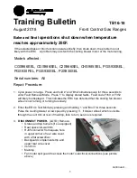
Ensure that proper 
clearance between wires 
and blower assembly will be 
maintained when rear wire 
cover is re-installed.

Remove the three hex screws 
securing blower and lift blower 
and duct assembly.  Push 
insulation beyond vertical flange 
of oven cavity.  

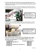
4. Check for foreign objects in the blower wheel.  The wheel should rotate freely by hand 

without noise or undue friction.  Be sure nothing is pressing against the red hub on the end 
opposite the motor.  Re-route any wires, such as the RJ45 connector leads, that may lie in 
contact with the motor shaft.

5. Visually check wire connections to the low speed (black wire) and high speed (red wire) 

tabs of the blower motor.  Check connection to the Neutral (white wire) tab.  Make sure the 
gray plastic six-pin connector is fully engaged.

6. Power up range.  Check for blower operation again using Test Mode (Step 2).  If blower 

now operates, look for insulation pushing up on blower that would cause binding when 
fully assembled.

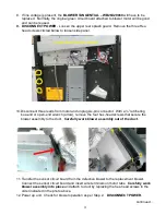
7. Press 

3

again and, if still no operation, check for line voltage between the low speed 

(black wire) and neutral tabs.   Also check for line voltage at the ERC between J903 pin 1 
and neutral.  If line voltage is not present, 

DISCONNECT POWER

and replace the 

MACHINE BOARD WITH FRAME

.

Full Model Number

Part Number of Machine Board

CGS986EEL1ES, CGS986SEL1SS

WB27X29498

C2S986SEL1SS

WB27X29493

CHS985SEL1SS

WB27X29496

PGS930BEL1TS, PGS930FEL1DS, PGS930SEL1SS

WB27X29497

P2S930SEL1SS

WB27X29501

2

continued…

Содержание GE CGS986EEL

Страница 1: ...ng too slowly 2 Enter the ERC s Test Mode by pressing and holding 1 and Broil for three seconds Pulse the cooling blower at low speed by pressing 3 If blower wheel which is visible through the vent trim at rear of maintop fails to turn service is required 3 DISCONNECT POWER LOTO Remove Grates and top burners if so equipped Rear spacer to wall trim RJ45 connector from square hole in upper corner of...

Страница 2: ...ed red wire tabs of the blower motor Check connection to the Neutral white wire tab Make sure the gray plastic six pin connector is fully engaged 6 Power up range Check for blower operation again using Test Mode Step 2 If blower now operates look for insulation pushing up on blower that would cause binding when fully assembled 7 Press 3 again and if still no operation check for line voltage betwee...

Страница 3: ...nnector With a ratcheting box end or open end wrench arrow remove the four hex head screws that secure the blower assembly to the duct Carefully work blower assembly out of the duct 11 Transfer the sensor circuit board from the defective blower to the replacement blower Connect the sensor circuit board and insert wire terminals on motor tabs Carefully work blower assembly into place and attach to ...

Страница 4: ...hillips screws in rear splash guard Motor spill guard Maintop Vent trim RJ45 connector to square hole of rear wire cover Backguard complement strip and rear wire cover Rear spacer to wall trim Top burners and grates 14 Power unit and check for cooling blower operation one more time per Step 2 Start a self clean cycle and listen for rattles with fan operating at high speed then cancel self clean op...

Отзывы: