background image


SERVICE MANUAL


Model: CFE629CW 

22

Issue  2009-12-23 

Rev.  Ref0912S021V0 

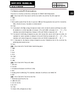
7-2. Main control PCB connections


There are 4 connectors on the main control panel of CFE/AFL/AFD refrigerators.   

CN1

 is the connector for the sensors and the door switch. Its pins from the left to right are: 

1: GND 
2: +12V 
3: Door switch signal. When the door is opened, GND and the signal wires are switch to conduction. 

When the door is open, the wires are disconnected;   

4-6: Null 
7-8: Connected to the fridge storage temperature sensor. We can test the sensor with these two wires. 

Its resistance in normal operation is between 6.35 and 3.88k

 (correspond to 0

℃~

10

). The 

resistance at normal temperature is between 2.45 and 1.58k

 (correspond to 20

℃~

30

);  

7-9: Connected to defrosting temperature sensor. We can test the sensor with these two wires. Its 

resistance in normal operation is between 10.9 and 25.19k

 (correspond to -10

℃~

-25

). The 

resistance at normal temperature is between 2.49 and 1.61k

 (correspond to 20

℃~

30

);  

10-11: Connected to the freezer storage temperature sensor. Resistance test is the same as the 

defrosting temperature sensor; 

12: Null 

CN2

 is the connector for the LED lamps and display panel: 

1: GND 
2: +5V 
3: Com 
4: Com 
5-6: Null 
7: +12V 
8: GND 

CN3 

is the connector for the power cables 

1: Zero line 
2: Live line 
3: Compressor (between it and the zero line)   
4: Null 
5: Heating tube for defrosting. The resistance between it and the zero is 345

±10%  

6: Null 

CN4

 is the connector for the air door and fan: 

1: Feedback signal from the fan   
2: GND of the fan 
3: +12V of the fan 
4: fan +12V   
5-6: Null 
7-9: Motor of the refrigeration air door 

Содержание CFE633CSE

Страница 1: ...nicians only and is not designed for use by the general public It dose not contain warnings and cautions to advice non technical individuals of potential dangers in attempting to service a product Product powered by electricity should by serviced or repaired only by experienced professional technicians Any attempt to service or repair the product or products dealt with in this service information ...

Страница 2: ...ndle 10 3 2 Installing and Removing Door 10 3 2 1 Dismantle and install the front decoration 11 3 2 2 Dismantles and install the upper decoration strip and cables 11 3 2 3 Dismantle and install the middle and lower hinge 12 3 5 Removing the Air Duct 13 3 5 1 Removal of fridge air duct 13 3 5 2 Removal of freezing air duct 13 4 Control and display system 14 4 1 Control and display panel 14 4 1 1 Mo...

Страница 3: ... flow scenograph 20 7 Circuit diagram 21 7 1 Main Control PCB diagram 21 7 2 Main Control PCB connections 22 8 Trouble shooting 23 8 1 Common problems and solutions 23 8 1 1 food in the fridge storage compartment is frozen 23 8 1 2 the buzzer beeps to alarm 23 8 1 3 No defrosting 23 8 1 4 Neither displaying nor starting when powering on 24 8 1 5 Poor freezing effect accompanied by loud noise 24 8 ...

Страница 4: ...wear intact cotton gloves when repair any parts of the evaporator so that scratches by the sharp fins can be avoided 8 If there is a breakdown with the refrigeration system please surrender the machine to the service center else the leaked refrigerant may pollute the atmosphere 9 The refrigerator use AC of 220V with a frequency of 50Hz 10 A big fluctuation of voltage exceed the range 187 230V may ...

Страница 5: ...in the table below Note A note provides information that is not indispensable but may nevertheless be valuable to the reader such as tips and tricks Caution A caution is used when there is danger through incorrect manipulation may damage equipment loose data get an unexpected result or has to restart part of a procedure Warning A warning is used when there is danger of personal injury Reference A ...

Страница 6: ...2 Total net capacity L 290 Net capacity refrigerator compartment L 210 Net capacity freezer compartment ice compartment L 80 80 Freezing capacity kg 11kg Energy consumption year kWh 310 Max storage time at breakdown Freezer Min 16 Defrosting M manual A automatic A Frost free system yes Defrost water outlet yes Air circulating ventilator yes Kind of coolant R134a R600a R600a 52g 3 Technical data Vo...

Страница 7: ...3 Type gr grill g glass p plastic g Color w white b blue t transparent t Adjustable Y yes N not N Foldable Shelf No Bottle Rack No Drawers Plastic drawers fully freezing comp n 2 Half freezing comp n 1 Colour of drawer w white t transp g green t Crisper Chiller Meat salad crisper transparent white Chiller t Vegetable crisper s transparent white t 5 Equipment accessories Control panel Interior exte...

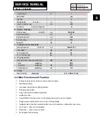
Страница 8: ...ng symbols Packing materials Recycling symbols RS RS RS Carton weight in gr 6270 Polystyrene weight in gr 06 2570 Polyethylene foil weight in gr 04 210 9 Service Users instruction languages D F I GB E P NL 2 2 Main Functions and Features Energy saving and convenience only in some models Half shelf structure Innovative long efficiency lighting system Foldaway wine holder Large crisper with humidity...

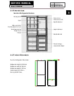
Страница 9: ...tor Dimensions Refrigerator height H 1880mm Refrigerator width W 595mm Refrigerator depth D 670mm Cabinet depth D1 576mm Door depth D2 78mm Turnover box Crisper Shelf Display panel Small bottle rack Large bottle rack Small bottle rack Freezer storage compartment drawer Fresh keeping box Crisper cover Turnover box rack Fresh keeping box cover Wire wine holder ...

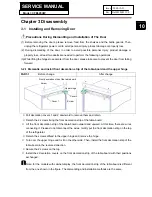
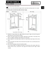
Страница 10: ...nge Pull decoration covers 1 and 2 downward to remove them and retain Detach the 2 screws fixing the front decoration strip of the table board Lift the front decoration strip of the table board outward and upward At this time there are wires connecting it Please do not disconnect the wires Gently put the front decoration strip on the top of the refrigerator Detach the screws affixed to the upper h...

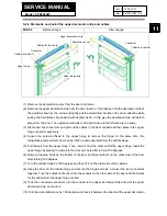
Страница 11: ... can be lifted up and separated from the middle hinge 5 Pull the axis from the upper hinge Then insert it from the other end of the upper hinge Insert the upper hinge by placing the axis into the door axis hole after turning 180 degrees 6 Remove the stop block on the bottom of the door and then reatacht on the other side of the door after turning 180 degrees 7 Turn the middle hinge by 180 degrees ...

Страница 12: ...antle the stop blocks on the bottom of the doors Turn them by 180 degrees and refit them on the other side 3 Tilt the refrigerator to the required angle Detach the screws fixing the lower hinge and remove the hinge 4 Fix the lower hinge to the bottom of the other side of the cabinet Then mount the lower door on the lower hinge 5 Take out the 3 hole plugs on the other side of the cabinet Turn the m...

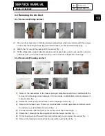
Страница 13: ... 3 3 2 Removal of freezing air duct 1 Take out the accessories in the freezer storage compartment which may interfere with the removal of the freezing air duct drawers of 2 door models middle bottom doors and drawers of 3 door models fig 2 Detach the screw in the harness cover over the freezing air duct fig 3 Remove the harness cover There is a small indentation on both upper side and bottom side ...

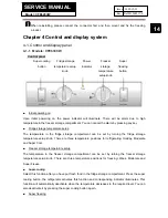
Страница 14: ...re setup The temperature in the fridge storage compartment can be set by turning the fridge storage temperature setup knob There are three temperature positions for refrigerating Holiday Moderate and Super Cool Freezer storage temperature setup The temperature in the freezer storage compartment can be set by turning the freezer storage temperature setup knob There are three temperature positions f...

Страница 15: ...finished It will be lit up by opening the door or pressing any key Alarm does not light up the display screen Door open alarming When the refrigerator door is open for more than 3 minutes the super cooling indicator will flash and the buzzer will sound 3 beeps every 30 seconds The buzzer can be silenced by closing the door or pressing any key Over temperature alarm When the temperature in the free...

Страница 16: ...F3 Display panel The fridge storage temperature sensor is located on the right side of the fridge storage compartment Malfunction of the freezer storage temperature sensor F SNR F4 Display panel The freezer storage temperature sensor is located on the left side of the freezing air duct cover Malfunction of the defrosting temperature sensor D SNR F6 Display panel The defrosting temperature sensor i...

Страница 17: ...ure sensor R SNR 2 The air door is closed from the beginning of defrosting until 15 minutes after the defrosting is finished 3 Upon initial powering on or resetting of the control panel the air door conducts a close and open cycle before acting according to the control conditions in item 1 4 The air door will be forced to conduct an open and close cycle if it has been closed for 1 hour After that ...

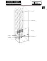
Страница 18: ... after the compressor has operated for 6 hours accumulatively 4 It may enter the defrosting state when the defrosting sensor is malfunctiony short circuit or open circuit In this case it will exit the defrosting state after 30 minutes Chapter 6 System flow principle 6 1 Refrigeration flow chart Principle diagram and description of the refrigeration cycle The refrigerant is compressed in the compre...

Страница 19: ...SERVICE MANUAL Model CFE629CW 19 Issue 2009 12 23 Rev Ref0912S021V0 ...

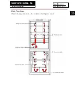
Страница 20: ...SERVICE MANUAL Model CFE629CW 20 Issue 2009 12 23 Rev Ref0912S021V0 6 3 Air Flow Chart Schematic drawing and description of air circulation in the refrigerator air duct ...

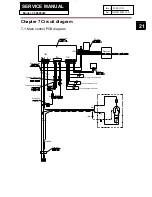
Страница 21: ...escaper connecting cable Fan motor connecting cable Electric air escaper Freezer storage temperature sensor Defrosting temperature sensor Fridge storage temperature sensor Heating tube 0064000353 C N P θ S R HT Power board LED Lamp Main control cable Display panel Switch Power cable Fan motor Fuse Yellow Green Blue Brown Yellow Green Blue Black Blue Brown Black Red ...

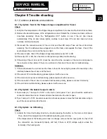
Страница 22: ... correspond to 20 30 7 9 Connected to defrosting temperature sensor We can test the sensor with these two wires Its resistance in normal operation is between 10 9 and 25 19kΩ correspond to 10 25 The resistance at normal temperature is between 2 49 and 1 61kΩ correspond to 20 30 10 11 Connected to the freezer storage temperature sensor Resistance test is the same as the defrosting temperature senso...

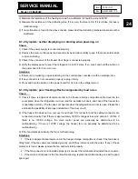
Страница 23: ... cabinet If there is no problem in this circuit the air door is malfunctioning Solutions 1 If the seal between the air door and the foam is found to be not tight please affix seal strip on the interface between the air door and the foam 2 If the sensor R1 is malfunctioning please replace it with a new one 3 If the main control panel is malfunctioning please replace it with a new one 4 If the conne...

Страница 24: ...ct accompanied by loud noise Check 1 Check if there is apparent abnormal sound in the freezer storage compartment Remove the fan cover plate close the refrigeration air door and the icemaker air door and check if the freezer fan is operating normally The fan does not operate when the refrigeration air door is open Please first eliminate the possibility of improper installation of the door on off 2...
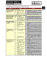
Страница 25: ...idge storage compartment does not work z The air door cable is not connected properly z The fan does not work z The fridge storage compartment is turned off z Check if the air door cable is not connected properly and install it correctly if not so Verify that the air door acts normally with the Fridge ON OFF key on the display panel z The fan does not work while the refrigeration air door is open ...
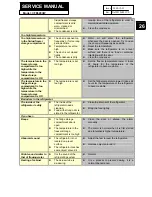
Страница 26: ...e of the refrigerator to become stable The temperature in the fridge storage compartment is too high while the temperature in the freezer storage compartment is OK z The temperature is set too high z Set the fridge temperature lower It takes 24 hours for the temperature of the refrigerator to become stable Bad odors in the refrigerator The inside of the refrigerator is dirty z The inside of the re...

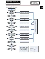
Страница 27: ...is tight contact is good Whether input and output voltage of main control board is normal Whether each contact of main control board is normal Tighten each contact and test machine again Y Trouble of lighting and display system Adjust the grade according to fact Compressor is open circuit or short circuit Inner trouble of compressor If it is infinite or 0 then the starter is out of work Heat prote...

Страница 28: ...SERVICE MANUAL Model CFE629CW 28 Issue 2009 12 23 Rev Ref0912S021V0 Sincere forever Haier Group Haier Industrial Park No 1 Haier Road 266101 Qingdao China http www haier com ...

Отзывы: