Haier 24E2000 Скачать руководство пользователя страница 9


3. Location of Controls and Components 3-1 Component Location 


3-2 Main Board   


No. 


Component 


1   

Keypad   

2   

Backlight wire   

3   

Panel T-con Board   

4   

IR board wire   

5   

Key pad board wire 

6   

LVDS cable 

7   

Main board   

IR board   

Speaker 


Содержание 24E2000

Страница 1: ...ls of potential dangers in attempting to service a product Products powered by electricity should be serviced or repaired only by experienced professional technicians Any attempt to service or repair the product or products dealt with in this service information by anyone else could result in serious injury or death ...

Страница 2: ...omponent Location 8 3 2 Main Board 8 3 3 LED Panel 11 4 Disassembly Procedures 12 5 Accessories 17 6 Installation Instructions 18 6 1 Power Connection 18 6 2 External Equipment Connections 19 7 Operation Instructions 25 7 1 Side Control 25 7 2 Rear Terminals 26 7 3 Using Remote Control 27 8 Electrical Parts 28 8 1 System Block Diagram 28 8 2 Circuit Diagram 29 8 3 Wiring Connection Diagram 35 ...

Страница 3: ... Mode 47 9 3 Software Update 48 9 4 Hotel Mode 48 10 Troubleshooting 49 10 1 Simple Check 49 10 2 System Power Check 50 10 3 No Sound No Picture 51 10 4 Audio Problem 52 10 5 Video Problem 53 10 6 Main board not work 54 10 7 Panel not work 54 10 8 Power board not work 54 ...

Страница 4: ...roduct This symbol indicates that there are important operating and maintenance instructions in the literature accompanying the appliance 1 2 2 Be careful to the electrical shock To prevent damage which might result in electric shock or fire do not expose this TV set to rain or excessive moisture This TV must not be exposed to dripping or splashing water and objects filled with water such as vases...

Страница 5: ...s assemblies 5 Unless specified otherwise in this service manual clean electrical contacts only by applying the following mixture to the contacts with a pipe cleaner cotton tipped stick or comparable non abrasive applicator 10 by volume Acetone and 90 by volume isopropyl alcohol 90 99 strength CAUTION This is a flammable mixture Unless other specified in this service manual lubrication of contacts...

Страница 6: ... can generate electrical charges sufficient to damage ES devices 5 Do not use freon propelled chemicals These can generate electrical charges sufficient to damage ES devices 6 Do not remove a replacement ES device from its protective package until immediately before you are ready to install it Most replacement ES devices are packaged with leads electrically shorted together by conductive foam alum...

Страница 7: ...e below Note A note provides information that is not indispensable but may nevertheless be valuable to the reader such as tips and tricks Caution A caution is used when there is danger that the reader through incorrect manipulation may damage equipment data loss get an unexpected result or has to restart part of a procedure Warning A warning is used when there is danger of personal injury Referenc...

Страница 8: ...uage English Spanish France Video Audio System NTSC M ATSC Dimensions with Stand W x H x D 28 78 x18 89 x6 69 Dimensions w o Stand W x H x D 28 78 x17 22 x2 66 Weight with Stand 13 89 lbs Weight without Stand 9 92 lbs Wall Mount Pattern H x V 200 x 100 mm Wall Mount Screw Type M6 x 12 mm Power Consumption 36W Standby 0 5W Mains Power 12V 3A adapter Audio Power 2 5W 2 5W ...

Страница 9: ...ion of Controls and Components 3 1 Component Location 3 2 Main Board No Component 1 Keypad 2 Backlight wire 3 Panel T con Board 4 IR board wire 5 Key pad board wire 6 LVDS cable 7 Main board 8 IR board 9 Speaker ...

Страница 10: ...ED Key pad CN6 To Speaker CN18 Pin No Signal Name Description 1 GND Ground 2 K7 3 K6 4 K5 5 K4 6 K3 7 K2 8 K1 9 K0 10 GND Ground 11 IR IR receiver 12 GRN LED Blue 13 RED LED Red 14 5V 5V DC Power Supply Pin No Signal Name Description 1 ROUT Audio Right Channel Output 2 ROUT Audio Right Channel Output 3 LOUT Audio Left Channel Output 4 LOUT Audio Left Channel Output ...

Страница 11: ...10 3 3 LED Panel 3 4 1 Connector Definition Pin No Signal Name Description 1 RSPK Speaker R 2 ROUT Speaker R 3 LOUT Speaker L 4 LSPK Speaker L ...

Страница 12: ...11 4 Disassembly Procedures 1 Remove the screws securing the back cover Red block with Torque 4 4 5 kgf cm yellow block with Torque 5 5 5 kgf cm 2 Detach the back cover from the left side of the unit ...

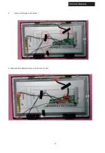
Страница 13: ...12 3 Remove all tapes on the cables 5 Disconnect the cables and remove them from the unit ...

Страница 14: ...13 6 Remove the screws securing the main board power board side I O cover and bottom I O cover then remove them from the unit Torque 3 8 0 3 kgf cm ...

Страница 15: ...14 Manual 4 Accessories Remote Control 2 x AAA Batteries User Manual ...

Страница 16: ...ert the adapter into a standard polarized AC outlet Never connect the adapter to a voltage other than specified If you cause a static discharge when touching the unit and the unit fails to function simply unplug the unit from the adapter outlet and plug it back in The unit should return to normal operation ...

Страница 17: ...ection you used HDMI Component Composite etc Connecting to an antenna cable wall jack Connect one end of a coaxial cable not included to the ANT IN jack on the back of your TV then connect the other end of the cable into the antenna or cable TV wall outlet Note To improve picture quality from an antenna in a poor signal area install a signal amplifier If you need to split the antenna signal to con...

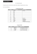
Страница 18: ...17 Connecting a PC VGA Supported timing ...

Страница 19: ...18 Service Manual Connecting AV Equipment COMPONENT OUT ...

Страница 20: ...mponent or composite device at a time When connecting a composite video source connect the yellow video wire to the Y green jack Connecting A Digital Audio Device and Headphones Note Turn off the TV set and external devices before making connections When headphones are inserted the TV speakers will be muted ...

Страница 21: ...20 Cable Sample Note The cables are not included in the package ...

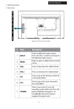
Страница 22: ...21 7 Operation Instructions 7 1 Side Control ...

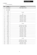
Страница 23: ...22 7 2 Rear Terminals Connector Descriptions Ser 9 P r e s s t o o p e n t h e ...

Страница 24: ...23 t e l e t e x t C C 7 3 Using Remote Control ...

Страница 25: ...24 8 Electrical Parts 8 1 System Block Diagram ...

Страница 26: ...25 8 2 Circuit Diagram ...

Страница 27: ...26 ...

Страница 28: ...27 ...

Страница 29: ...28 ...

Страница 30: ...29 ...

Страница 31: ...30 ...

Страница 32: ...31 2 2 0 ...

Страница 33: ...32 No Connection 1 Connection wire for Speaker 2 Connection wire for Back light 3 Connection wire for LVDS wire 4 Connection wire for IR Key pad ...

Страница 34: ...33 9 Measurements and Adjustment 9 1 Operation Guide ...

Страница 35: ...34 ...

Страница 36: ...35 ...

Страница 37: ...36 ...

Страница 38: ...37 ...

Страница 39: ...38 ...

Страница 40: ...39 ...

Страница 41: ...as LVDS map Logo Power White pattern PWM Hotel Mode and Language type PICTURE To adjust the picture settings such as Backlight W B Adjust PQ Nonlinear Color Setting Luma_other Peaking Setting NR Setting CTI Setting Gamma DLC and VIP SOUND To adjust the sound settings such as Sound Mode Volume Curve and Audio Output ADC ADJUST To perform ADC adjusting System Info To view software information Softwa...

Страница 42: ... updating will start and the progress bar will be displayed 5 When the update is completed the TV will turn off and on again automatically Note Before performing software update check the version of the current software and the update file first 9 4 Hotel Mode Hotel mode allows user to set certain default settings limit access to certain controls and adjustments so that settings cannot be altered ...

Страница 43: ...l by pressing button on the remote control or VOL button on TV side control panel Press button on the remote control to ensure mute is off Good sound but poor color Adjust the contrast color and brightness settings Poor picture Poor picture quality may occur when an activated S VHS camera or camcorder is connected to your TV and the other peripheral at the same time Switch off one of the periphera...

Страница 44: ...43 10 2 System Power Check ...

Страница 45: ...44 10 3 No Sound No Picture ...

Страница 46: ...45 10 4 Audio Problem ...

Страница 47: ...46 10 5 Video Problem 1 Check C69 for Y ...

Страница 48: ...output of boost IC is working normally Verify if the Mainboard output the right On Off signal to power board Verify if the Mainboard output the LVDS singal to panel T con board Verify if the software is the right version of this model Change the LVDS wire to check if it s broken 10 8 Power board not work Verify if the power cord connect well Check if the power supply is working normally Check if t...

Страница 49: ...48 Sincere Forever Haier Group Haier Industrial Park No 1 Haier Road 266101 Qingdao China http www haier com Printed in China ...

Отзывы: