background image

(This function is unavailable on 
some models)

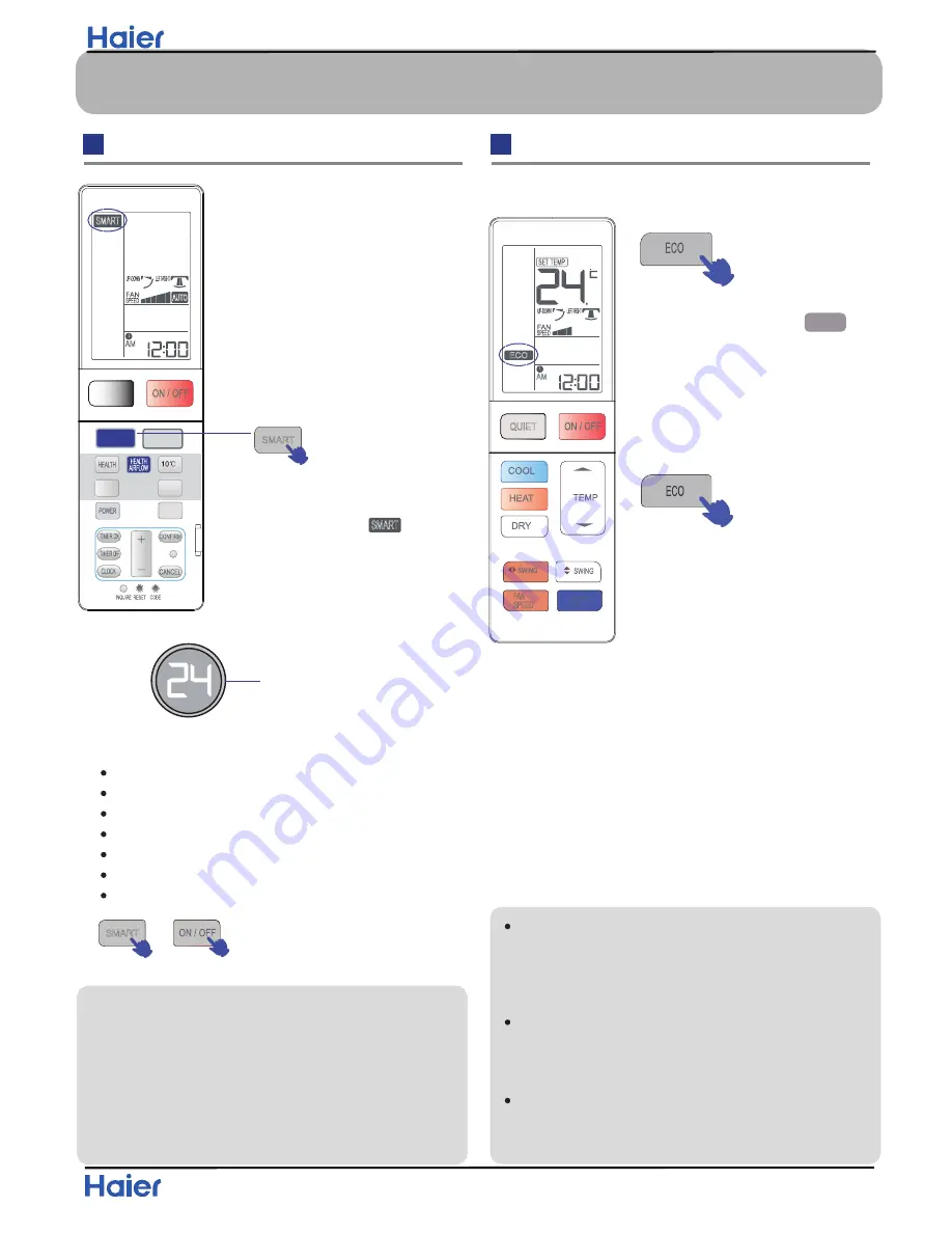
One key can give you a 
comfortable room!
The air conditioning unit can 
judge the indoor temperature and 
humidity, and make the adjustment 
accordingly.

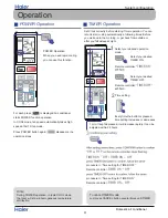
SMART start

aureol: “ white”

 or 

 SMART stops

Press ON/OFF button, unit starts. 
Press SMART button “

” is 

displayed on the remote controller 
Now, the display board of the air 
conditioning unit will turn WHITE.

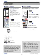
Automatic adjusting with the environmental temperature, 

running with power saving.

Under the cooling, heating and dehumidifying mode, 

press the smart key to enter the smart function. Under 

the smart running mode, when the air conditioning is 

running, it will automatically select cooling, heating, 

dehumidifying or blowing mode as When the smart 

function is running, press the “cooling” “heating” or 

“dehumidifying” key to switch to the other mode, you 

will exit from the smart function.

The power saving function only works under the 

cooling, heating or dehumidifying mode, after the 

power saving function is set, press the sharp, 

mute, sleep, or smart key to exit the power saving 

function.
After the power saving is set, the host machine will 

automatically adjust the setting temperature, and 

automatically control the switch of the compressor,

which may be inconsistent with the user’s setting.
The power saving function is more effective after 

the air conditioning has been running for a long 

time (more than 2 hours)

SMART FRESH
SMART Defrost
SMART FAN SPEED
SMART FAN HEALTH
SMART DRY
SMART SOFT
SMART Control temperature

SMART Operation

ECO Operation

QUIET

SMART

SLEEP

LIGHT

CHILD

 LOCK

FRESH

SMART

AUTO

AM

SMART

ECO

AM

FAN

SPEED

ECO

QUIET

.

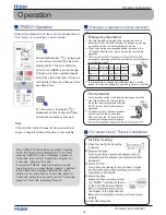
Press ECONOMY button “

ECO

” is 

displayed on the remote controller,

unit will run in ECONOMY operation.

Press ECONOMY button 

again, ECONOMY disappears, 

the operation stops. 

Operation

System configuration

Domestic air conditioner

33

Содержание 1U12BE2ERA

Страница 1: ... of potential dangers in attempting to service a product Products powered by electricity should be serviced or repaired only by experienced professional technicians Any attempt to service or Repair the product or products dealt with in this service information by anyone else could result in serious injury or death WARNING 2014 Qingdao Haier Air Conditioner General corp Ltd All rights reserved Unau...

Страница 2: ... 8 4 Piping diagrams 9 5 Operation range 10 6 Printed Circuit Board Connector Wiring Diagram 11 7 Functions and Control 8 Dimensional drawings 9 Conter of gravity 10 Installations 11 Service Diagnosis 12 Performance and cerves diagrams 13 Sound level 14 Circuit diagrams 16 60 52 35 31 30 30 61 ...

Страница 3: ...me explanation 1 U 1 2 B E 2 E A R The maximum combination number Type of outdoor unit U normal type Nominal cooling capacity 12000BTU h Platform of outdoor units B B platform Europe Version number Heat pump R410A refrigerant DC inverter Apply toT1 208 230V60HZ 1ph 1 ...

Страница 4: ...t before disassembling the equipment for a repair Working on the equipment that is connected to a power supply can cause an electrical shook If it is necessary to supply power to the equipment to conduct the repair or inspecting the circuits do not touch any electrically charged sections of the equipment If the refrigerant gas discharges during the repair work do not touch the discharging refriger...

Страница 5: ...e welder in an enclosed room can cause oxygen deficiency 1 2 2 Cautions Regarding Products after Repair Warning Be sure to use parts listed in the service parts list of the applicable model and appropriate tools to conduct repair work Never attempt to modify the equipment The use of inappropriate parts or tools can cause an electrical shock excessive heat generation or fire When relocating the equ...

Страница 6: ...ified power cable can cause an electrical shock or fire Placing heavy items on the power cable and heating or pulling the power cable can damage the cable Do not mix air or gas other than the specified refrigerant R 410A R22 in the refrigerant system If air enters the cooling system an excessively high pressure results causing equipment damage and injury If the refrigerant gas leaks be sure to loc...

Страница 7: ...an electrical shock or fire If the power cable and lead wires have scratches or deteriorated be sure to replace them Damaged cable and wires can cause an electrical shock excessive heat generation or fire Warning Do not use a joined power cable or extension cable or share the same power outlet with other electrical appliances since it can cause an electrical shock excessive heat generation or fire...

Страница 8: ... attention of the reader to specific information The meaning of each icon is described in the table below 1 2 5 Using Icons List Icon Type of Information Description Note Note A note provides information that is not indispensable but may nevertheless be valuable to the reader such as tips and tricks Caution Caution A caution is used when there is danger that the reader through incorrect manipulati...

Страница 9: ... e W 24 75 lb t h g i e w s s o r G Sound level e r u s s e e p d n u o S r e w o p d n u o S ELECTRICAL SPECIFICATIONS cooling heating Nominal running current A 5 2 5 7 Maximum running current A 6 2 6 4 Starting current A 1 2 1 2 TECHNICAL SPECIFICATIONS PARTS g n i t a e h g n i l o o c Compressor r o s s e r p m o C y r a t o R e p y T 1 2 D K Z 2 9 0 S R 5 l e d o M 0 0 7 Btu t u p t u o r o t...

Страница 10: ...emational Protection degree IP 24 Note the data are based on the conditions shown in the table below h t g n e l g n i p i P g n i t a e h g n i l o o c Indoor 80 6 F DB 66 2 F W B Outdoor 95 F DB 75 2 F W B Indoor 68 F DB Outdoor 44 6 F DB 42 8 FWB 16 4in 3 Sensors list type Description Qty Ambient sensor Its used for detecti 1 e d i s r o o d t u o f o e r u t a r e p m e t g n Suction sensor It...

Страница 11: ...Pinping diagrams Domestic air conditioner 4 Pinping diagrams 9 ...

Страница 12: ...Operation range Domestic air conditioner 5 Operation range 10 F F 68 86 104 122 64 4 109 4 114 8 50 68 86 60 8 73 4 89 6 50 68 86 14 19 4 23 32 41 50 59 68 77 75 2 F F 16 4in in ...

Страница 13: ...nit 5 CN8 Connector for CN2 CN1 on the module board 6 CN9 7 CN10 Connector for four way valve coil 8 CN16 Connector for electric expansion valves 9 CN17 Connector for thermistors 10 CN18 11 CN19 12 CN20 13 CN21 Connector for fan motor 14 CN22 Connector for DC POWER 15Vand 5V to the module board 15 CN23 Connector for communicate between the control board and the module board 16 CN24 Connector to P ...

Страница 14: ...ctor for the U V W wire of the compressor 6 CN3 7 CN4 8 CN10 Connector for the DC power 5V and 15V form the control PCB 9 CN11 Connector for communicate between the control board and the module board Notes Other Designations PCB 1 Control PCB 1 FUSE 1 25A 250VAC FUSE 2 1A 250VAC 2 LED 1 Keep light representative normal if keep flash interval representative trouble Alarm 3 RV1 RV2 RV3 Varistor 12 ...

Страница 15: ...Wiring diagrams Domestic air conditioner PCB 1 CN1 CN2 CN3 CN22 CN8 CN9 CN21 CN10 CN17 CN18 CN19 CN20 CN23 CN24 CN26 CN4 CN16 CN5 CN6 13 ...

Страница 16: ...CN1 CN2 CN3 CN4 CN5 CN6 6 CN7 PCB 2 Dom Wirin mestic air co ng diagrams onditioner CN1 CN1 s 11 10 14 ...

Страница 17: ...r different unit to double way air exchange motor air exchange motor to single way DEFROST TEMP SENSOR TEMP SENSOR TEMP SENSOR COMPRESSOR DISCHARGE TEMP SENSOR DC FAN MOTOR CN21 3 15A 250VAC FUSE2 CN11 Electric Heating Cable TO INDOOR UNIT TERMINAL BLOCK POWER CN36 Description LED1 Flash 1 2 3 4 8 6 5 13 19 18 12 10 Times 24 25 Outdoor EEPROM error The protection of IPM Communication fault Overcur...

Страница 18: ... should be prior to the calculated frequency 7 1 1 3 The speeds of increasing or decreasing the frequency of the compressor The speed of increasing or decreasing the frequency rapidly 1 1HZ second The speed of increasing or decreasing the frequency slowly 2 1HZ 10seconds 7 1 1 4 The calculation of the compressor s frequency 1 The minimum maximum frequency limitation A While cooling F MAX r is the ...

Страница 19: ...ture and under the condition of maximum ability the maximum designing ability of the system ΔT ΔTi Pi Pi ΔTi Tst_i the setting temperature Tnh_i the indoor environment temperature Pi i the ability of the indoor unit Cooling dehumidification mode Heating mode K Ki Pi Pi The calculation of the actual output frequency when there is no healthy airflow F F ED rated frequency P K When the healthy airflo...

Страница 20: ...valve control see the defrosting process Four way working in other ways Under the mode of heating open the four way valve when the compressor is not started or changed to non heating mode make sure the compressor is stoped for 2 minutes and then close the four way valve 7 1 4 Protection function 7 1 4 1 TTC high temperature preventing protection Once the machine is started it can run TTC air blowi...

Страница 21: ...essor stops Fgh_t1 149 F Fgh_t1 2 Fgh_t2 2 N Decreasing the frequency rapidly Fgh_t2 138 2 F P Decreasing the frequency slowly Fgh_t3 131 F Fgh_t3 2 Fgh_t4 2 Q Prohibiting increasing the frequency Fgh_t4 123 8 F R Increasing slowly Fgh_t5 116 6 F Fgh_t5 2 Normal N Decreasing at the speed of 1HZ 1 second P Decreasing at the speed of 1Hz 10 seconds Q Continue to keep the last time instruction cycle ...

Страница 22: ...n 7A the frequency of the compressor increases at the prohibited speed During the starting process of the compressor if the AC current is greater than 6 5A the frequency of the compressor increases at the speed of no faster than 0 1HZ second Remarks when the outdoor temperature is high there s compensation for AC current protection 1 When the outdoor environment temperature is higher than 104 F AC...

Страница 23: ...cooling coil When the defrosting temperature and the sensor s temperature are higher than 149 F the frequency of the compressor decreases 1hz 10seconds Keep the frequency until it decreases to the lowest frequency When the temperatures are lower than 149 Fand higher than 140 F keep the frequency of the compressor When the temperatures are lower than 140 F relieve the defrosting temperature protect...

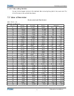
Страница 24: ...34 92 2 2 87 2775 79 6222 72 5729 28 87 34 88 0 4 82 5577 75 4384 68 8710 28 90 34 86 1 4 78 1230 71 5010 65 3815 28 94 34 83 3 2 73 9543 67 7939 62 0907 28 98 34 79 5 70 0342 64 3023 58 9863 29 01 34 77 6 8 66 3463 61 0123 56 0565 29 05 34 74 8 6 62 8755 57 9110 53 2905 29 08 34 72 10 4 59 6076 54 9866 50 6781 29 12 34 68 12 2 56 5296 52 2278 48 2099 29 16 34 65 14 53 6294 49 6244 45 8771 29 19 3...

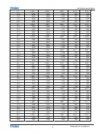
Страница 25: ... 33 57 68 12 7718 12 3223 11 8780 30 45 33 53 69 8 12 2280 11 8126 11 4011 30 51 33 49 71 6 11 7102 11 3267 10 9459 30 54 33 44 73 4 11 2172 10 8634 10 5114 30 60 33 40 75 2 10 7475 10 4216 10 0964 30 65 33 35 77 10 3000 10 0000 9 7000 30 65 33 35 78 8 9 8975 9 5974 9 2980 30 63 33 37 80 6 9 5129 9 2132 8 9148 30 56 33 34 82 4 9 1454 8 8465 8 5496 30 49 33 49 84 2 8 7942 8 4964 8 2013 30 43 33 55 ...

Страница 26: ... 2 4413 2 2700 27 93 35 83 147 2 2 5396 2 3611 2 1932 27 84 35 91 149 2 4591 2 2840 2 1195 27 75 35 98 150 8 2 3815 2 2098 2 0486 27 68 36 05 152 6 2 3068 2 1383 1 9803 27 59 36 12 154 4 2 2347 2 0695 1 9147 27 52 36 21 156 2 2 1652 2 0032 1 8516 27 43 36 28 158 2 0983 1 9393 1 7908 27 34 36 36 159 8 2 0337 1 8778 1 7324 27 27 36 43 161 6 1 9714 1 8186 1 6761 27 18 36 50 163 4 1 9113 1 7614 1 6219...

Страница 27: ... 0 7646 0 6867 24 48 38 80 215 6 0 8281 0 7436 0 6672 24 39 38 89 217 4 0 8061 0 7233 0 6484 24 28 38 98 219 2 0 7848 0 7036 0 6303 24 19 39 06 221 0 7641 0 6845 0 6127 24 08 39 15 222 8 0 7441 0 6661 0 5957 23 97 39 24 224 6 0 7247 0 6482 0 5792 23 88 39 33 226 4 0 7059 0 6308 0 5632 23 77 39 42 228 2 0 6877 0 6140 0 5478 23 67 39 49 230 0 6700 0 5977 0 5328 23 56 39 58 231 8 0 6528 0 5820 0 5183...

Страница 28: ...5535 3638 1938 27 05 36 21 8 6 4738 4141 4032 7098 3429 0191 27 09 36 21 10 4 4451 4586 3795 3910 3233 1039 27 10 36 19 12 2 4183 5548 3573 4260 3049 5312 27 14 36 18 14 3933 3289 3365 7336 2877 4527 27 16 36 16 15 8 3699 5139 3171 3148 2716 0828 27 19 36 14 17 6 3480 9407 2989 2460 2564 6945 27 21 36 12 19 4 3276 5302 2818 6731 2422 6139 27 25 36 10 21 2 3085 2854 2658 8058 2289 2164 27 27 36 10 ...

Страница 29: ...38 35 31 86 441 0535 402 2430 366 5175 28 42 35 29 87 8 420 1431 383 7151 350 1301 28 45 35 26 89 6 400 3242 366 1295 334 5542 28 49 35 24 91 4 381 5350 349 4341 319 7460 28 53 35 20 93 2 363 7176 333 5801 305 6645 28 58 35 17 95 346 8176 318 5216 292 2709 28 62 35 15 96 8 330 7839 304 2151 279 5286 28 65 35 11 98 6 315 5682 290 6199 267 4031 28 69 35 08 100 4 301 1254 277 6976 255 8620 28 72 35 0...

Страница 30: ...0 62 5006 60 2211 30 24 33 73 167 62 3423 60 1906 58 0609 30 29 33 69 168 8 59 9821 57 9770 55 9885 30 34 33 66 170 6 57 7223 55 8552 53 9998 30 38 33 60 172 4 55 5583 53 8210 52 0912 30 43 33 57 174 2 53 4856 51 8706 50 2591 30 47 33 51 176 51 5000 50 0000 48 5000 30 47 33 51 177 8 49 7063 48 2057 46 7083 30 47 33 53 179 6 47 9835 46 4842 44 9911 30 40 33 60 181 4 46 3286 44 8323 43 3452 30 33 33...

Страница 31: ...15 4489 14 4506 13 5047 27 91 35 89 244 4 14 9968 14 0149 13 0855 27 82 35 94 246 2 14 5599 13 5942 12 6811 27 75 36 01 248 14 1376 13 1879 12 2909 27 66 36 09 249 8 13 7294 12 7955 11 9144 27 59 36 16 251 6 13 3347 12 4165 11 5510 27 50 36 23 253 4 12 9531 12 0503 11 2003 27 43 36 30 255 2 12 5840 11 6965 10 8617 27 36 36 37 257 12 2270 11 3545 10 5348 27 27 36 45 258 8 11 8817 11 0240 10 2191 27...

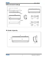
Страница 32: ...Dimensinal drawings Domestic air conditioner 8 Dimensional drawings 9 Center of gravity 30 0 24 0 18 0 22 2 57 0 84 1 78 2 76 2 57 0 84 0 84 0 84 0 39 2 57 1 1 78 ...

Страница 33: ...e than 5cm more than more than10cm more than 15cm more than 60cm A G A F C E D G B Arrangement of piping directions Rear left Left Rear right Right Below G Attention must be paid to the pitch of drain hose X Y X Z Dimensions inches Model x y z Hammer Place where the distance of more than lm from televisions radios wireless apparatuses and fluorescent lamps 3 feet or approximately In the case of fixi...

Страница 34: ...erials of indoor unit 2 Insert the indoor outdoor electric cable from backside of indoor unit and pull it out on the front side then connect them 3 Coat the flaring seal face with refrigerant oil and connect pipes Cover the tubing connection with insulation materials closely and with adhesive tape Fixing the indoor unit body Hang the unit body onto the upper notches of the mounting plate Move the b...

Страница 35: ...ble after installing the indoor unit When connecting the cable before installing the indoor unit Indoor unit Outdoor unit Max Elevation Amax 32 8ft 10m 09k 12k 50ft 15m 18k 24k In case the elevation A is more than 16 4ft 5m oil trap shoud be installed every 5 7m 16 4ft 23ft Max Length Bmax 50ft 15m 09k 12k 83 3ft 25m 18k 24k Insert the cord from the back side of the unit then pull it out on the fr...

Страница 36: ...Run 1 1 2 kg R410A 2 kg 2 1 B C D F E kg A This product contains fluorinated greenhouse gases covered by the Kyoto Protocol Do not vent into the atmosphere Refrigerant type R410A GWP value 1975 GWP global warming potential Please fill in with indelible ink 1 the factory refrigerant charge of the product 2 the additional refrigerant amount charged in the field and 1 2 the total refrigerant charge o...

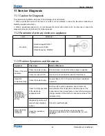
Страница 37: ...mission error occurs between the indoor and outdoor units In either case conduct the diagnostic procedure described in the following pages 11 2 Parameter of primary electronic appliance name parameter picture Compressor Rated voltage 220 230V Rated current 4 8A Rated frequency 50 60HZ Fan motor Rated voltage 220 230V Rated current 0 2A Rated frequency 50 60HZ Reactor Rated voltage 220 230V Rated c...

Страница 38: ... but does not cool or does not heat only for heat pump Check for faulty operation of the electronic expansion valve Set the units to cooling operation and compare the temperatures of the liquid side connection pipes of the connection section among rooms to check the opening and closing operation of the electronic expansion valves of the individual units Diagnosis by service port pressure and opera...

Страница 39: ...ommunication fault between the IPM and outdoor PCB Page45 F19 6 Power voltage is too high or low Page50 F27 7 Compressor is lock rotor or stopped momentary Page51 F4 8 Overheat protection for Discharge temperature Page46 2 4 e g a P t l u a f r o t o m n a f C D r o o d t u O 9 8 F F21 10 Defrost temperature sensor failure Page38 F7 11 Suction temperature sensor failure Page38 F6 12 Ambient temper...

Страница 40: ... resistance of thermistor using tester The relationship between normal temperature and resistance is shown in the value of indoor thermistor Thermistor resistance check YES NO YES Check the connector connection whether if it loose or misplug Re connect NO Replace the thermistor Replace the indoor PCB Is the resistance is conformity with normal temperature E1 Room temperature sensor failure E2 Heat...

Страница 41: ...the EEPROM are used to determine MCU when the data of EEPROM is error or the EEPROM is damaged Faulty EEPROM data Faulty EEPROM Faulty PCB Caution Be sure to turn off power switch before connect or disconnect connector or parts damage may be occurred Replace the indoor or outdoor mainboard Method of malfunction detection Malfunction detection conditions Troubleshooting Supposed causes 39 ...

Страница 42: ...on the indoor PCB the indoor pcb is damaged and need replace Pull out the terminals on the indoor mainboard and reinsert them Is it ok The fan speed detected by the Hall IC during fan motor running which is used to determine the fan motor operating When there is no fan speed feedback signal within 2 minutes Operation halt due to breaking of wire inside the fan motor Fan motor overheat protection O...

Страница 43: ...error or the EEPROM is damaged DC fan motor protection dues to the DC fan motor faulty DC fan motor protection dues to faulty PCB Caution Be sure to turn off power switch before connect or disconnect connector or parts damage may be occurred LED1 flash 9 times Outdoor diplay Method of malfunction detection Malfunction detection conditions Troubleshooting Supposed causes 41 ...

Страница 44: ...n YES Measure the voltage between 3 and 6 of the terminal about 0 5v Is it normal NO The motor of the outdoor unit is damaged and needs replacing Measure the voltage between 1 and 3 of the terminal of fan motor on the mainboard about DC310V Measure the voltage between 3 and 4 of the terminal about DC15V Measure the voltage between 5 and 3 of the terminal about 1 6v NO Is it normal The mainboard of...

Страница 45: ...functions are reported after it has run for some time Malfunction unsolved IPM protection is detected by checking the compressor running condition and so on The system leads to IPM protection due to over current The compressor faulty leads to IPM protection circuit component of IPM is broken and led to IPM protection IPM protection dues to the compressor faulty IPM protection dues to faulty PCB of...

Страница 46: ...YES NO The compressor is started normally but malfunctions are reported after it has run for some time Check the power supply is too low or too high NO Method of malfunction detection Malfunction detection conditions Troubleshooting he current of the compressor is too high when the IPM Module is damaged or the compressor is damaged power supply voltage is too low or too high Supposed causes LED1 f...

Страница 47: ...nboard with a new one Replace the outdoor IPM module with a new one NO NO Malfunction unsolved 1 Pull out and reinsert the terminals 2 Replace connected wire Method of malfunction detection Malfunction detection conditions Troubleshooting Communication is detected by checking the IPM module and the outdoor PCB The outdoor PCB broken leads to communication fault The IPM module broken leads to commu...

Страница 48: ... supply 310VDC with a multimeter check whether the power is 150 V or 390V Method of malfunction detection Malfunction detection conditions Troubleshooting An abnormal voltage rise or fall is detected by checking the specified voltage detection An voltage signal is fed from the voltage detection circuit to the microcomputer Supply voltage not as specified The IPM module is broken The outdoor PCB is...

Страница 49: ...re is below Pull out the exhaust sensor and measure its resistance at standard temperatures according to the resistance temperature table the results deviate much The sensor is damaged Replace the sensor with a new one The outdoor mainboard is damaged and needs be replaced NO NO Method of malfunction detection Malfunction detection conditions Troubleshooting The Discharge temperature control is ch...

Страница 50: ...Reconnect the linking cable 2 Replace the linking cable with new one Method of malfunction detection Malfunction detection conditions Troubleshooting Communication is detected by checking the indoor PCB and the outdoor PCB The outdoor PCB broken leads to communication fault The indoor PCB broken leads to communication fault Communication wiring disconnected The indoor PCB is broken The outdoor PCB...

Страница 51: ...with a multimeter If 230VAC is available but 310DC not the power module is damaged replace it with a new one Test the outdoor power supply 230VAC and 310VDC with a multimeter The outdoor mainboard is damaged replace it with a new one The indoor mainboard is damaged replace it with a new one If the value varies between 0 and 80 VAC the outdoor mainboard is damaged replace it with a new one If the v...

Страница 52: ...times IPM Module is damaged and needs replacing the Malfunctions exist also the compressor is damaged replace a new one NO Malfunction unsolved Maybe there is some disturbance Method of malfunction detection Malfunction detection conditions Troubleshooting The position of the compressor rotor can not detected normally when the wiring of compressor is wrong or the connection is poor or the compress...

Страница 53: ...s 2 Reinstall the fan Use some tools to measure the pressure of system NO NO Method of malfunction detection Malfunction detection conditions Troubleshooting High work intense control is activated in the heating mode if the temperature being sensed by the heat exchanger thermistor exceeds the limit Activated when the temperature being sensed by the heat exchanger rises above 149 F twice in 30 minu...

Страница 54: ...71 6 60 8 F 2623 2597 4301 3922 3587 3388 3189 2345 77 64 4 F 2777 2700 4428 4175 3786 3587 3468 2592 80 6 66 2 F F 2854 2751 4512 4301 3906 3707 3547 2654 86 71 6 F 3034 3009 4850 4639 4265 4105 3986 2993 89 6 73 4 F 3060 3034 4934 4723 4344 4145 4026 3024 89 6 75 2 F 3111 3086 5018 4808 4424 4225 4105 3086 1000 1500 2000 2500 3000 3500 4000 4500 5000 5500 cooling capacity W cooling capacity and ...

Страница 55: ... 653 71 6 60 8 F 454 463 1206 1247 1281 1362 1423 720 77 64 4 F 77 64 4 F 468 474 1179 1274 1321 1396 1464 746 80 6 66 2 F 491 483 1206 1301 1342 1409 1491 753 86 71 6 F 497 503 1254 1355 1403 1504 1572 806 89 6 73 4 F 505 494 1267 1396 1423 1531 1592 899 89 6 75 2 F 514 486 1288 1423 1443 1559 1613 966 100 300 500 700 900 1100 1300 1500 1700 power consumption w indoor tempe DB WB power consumptio...

Страница 56: ...mp humidity 46 indoor temp DB WB 60 8 F 66 2 F 71 6 F 59 F 2421 2504 2588 77 F 3239 3273 3339 86 F 3239 3306 3339 95 F 3273 3339 3439 104 F 3306 3473 3473 113 F 2554 2554 2652 1500 2000 2500 3000 3500 4000 59 F 77 F 86 F 95 F 104 F 113 F discharge pressure Outdoor Temp cooling discharge pressure 60 8 F 66 2 F 71 6 F 54 ...

Страница 57: ...tdoor temp humidity 46 indoor temp DB WB 60 8 F 66 2 F 71 6 F 59 F 660 683 706 77 F 883 893 911 86 F 883 902 911 95 F 893 911 938 104 F 902 947 947 113 F 696 696 723 350 450 550 650 750 850 950 1050 59 F 77 F 86 F 95 F 104 F 113 F suction pressure Outdoor Temp cooling suction pressure 60 8 F 66 2 F 71 6 F 55 ...

Страница 58: ... e t r o o d t u o DB WB 59 F 68 F 77 F 5 F 2338 1776 1905 23 F 3594 3286 3031 41 F 4676 4240 3940 44 6 42 8 F 4473 4167 3779 59 F 3660 3472 2955 68 F 3366 3248 2703 77 F 3472 3360 2783 0 500 1000 1500 2000 2500 3000 3500 4000 4500 5000 heating capacity W heating capacity and indoor outdoor temp curves 59 F 68 F 77 F 56 5 F 2 3 F 4 1 F 4 4 6 4 2 8 F 5 9 F 6 8 F 7 7 F ...

Страница 59: ...n i p m e t r o o d t u o DB WB 59 F 68 F 77 F 5 F 881 949 1037 23 F 1057 1044 1261 41 F 1193 1356 1437 44 6 42 8 F 1094 1204 1315 59 F 628 688 748 68 F 463 482 524 77 F 465 487 526 0 200 400 600 800 1000 1200 1400 1600 5 F 23 F 41 F 44 6 42 8 F 59 F 68 F 77 F cooling capacity w outdoor tempe DB WB heating capacity and indoor outdoor temp curves 59 F 68 F 77 F 57 ...

Страница 60: ...oor temp DB WB 59 F 68 F 77 F 5 F 2941 3069 3165 14 F 3005 3101 3197 23 F 3053 3133 3229 32 F 3101 3165 3261 41 F 3165 3197 3293 50 F 3062 3154 3200 59 F 2567 2644 2669 68 F 2459 2507 2531 1000 1500 2000 2500 3000 3500 4000 5 F 14 F 23 F 32 F 41 F 50 F 59 F 68 F discharge pressure Outdoor Temp heating discharge pressure 59 F 68 F 77 F 58 ...

Страница 61: ...p humidity 46 indoor temp DB WB 59 F 68 F 77 F 5 F 743 775 799 14 F 759 783 808 23 F 771 791 816 50 F 783 799 824 41 F 799 808 832 50 F 774 797 808 59 F 649 668 674 68 F 621 633 639 400 500 600 700 800 900 5 F 14 F 23 F 50 F 41 F 50 F 59 F 68 F suction pressure Outdoor Temp heating suction pressure 59 F 68 F 77 F 59 ...

Страница 62: ...tioner 13 Sound level Model Sound power level Indoor unit Sound power level Outdoor unit cooling heating 230V 60HZ Measuring location of microphone Cooling heating 1U12BE2ERA 62 60 68 86 104 122 140 158 176 68 86 104 122 140 158 176 ...

Страница 63: ...eed AC Fan E valve White R55 1K R56 1K R57 1K R58 1K R67 1K R72 1K R71 1K R70 1K 5V 1 2 CN33 SW TEST BLUE CX7 104 275V R48 10K XQ Red C11 104 50V R62 10K P2 2SA1037AK R60 10K R61 2K R59 2K FUSE2 T1A 250V W B R53 10K R52 10K R51 10K FUCTION TEST White TEST SS COOL HEAT PC GND 白 5V R85 10K R66 1K R84 4 7K R68 1K R69 1K N3 2SC2412K N4 2SC2412K White ERROR 1 2 3 CN17 D5 LL4148 D6 LL4148 Yellow Green 1...

Страница 64: ...0U 25V R17 330 1W 15V R32 5 1K 1 R30 1K R28 5 1K 1 R31 1K C5 104 50V R25 10K R26 1K R16 2 1W R14 100K 2W R15 15 C4 103 50V 9 10 5VD T1 Comment E22034 7 6 4 5 CY8 472 1KV R27 10K 1 3 R24 5 1K 1 CX5 104 275V ADJ 1 FB 2 CS 3 GND 4 HV 8 NC 7 VCC 6 DRV 5 IC1 NCP1200P100 D9 MUR115 MUR130 ER106 D10 ER106 D8 MBR3100 ER302 4 3 1 2 IC2 PC817A R20 220 R21 220 M1 IRFUC20 1 2 3 CN22 模块板电源 蓝 J11 R90 0 N P 1 CN2...

Страница 65: ... 104 C 208 104 IC 5 HA17393AF IC 6 HA1630D06 IC 6 HA1630D06 R 221 140 R 216 10 R 224 4 7K R 211 1K R 212 9 1K R 209 1K R 223 330 R 210 6 8K R 214 100 R 207 1K 5V TR1 M M BT9013 5V 15V IC 7 TLP251 2 3 5 6 8 4 8 5 6 7 R 015 330 R 208 6 8K R 014 330 R 013 330 R 018 4 7K R 016 1K R 012 4 7K R 011 4 7K R 008 4 7K R 019 4 7K R 213 100 1 2 3 4 5 6 7 8 IC 4 HA1630D06 IC 4 HA1630D06 R 206 1K R 205 1K R 203...

Страница 66: ...iagrams Domestic air conditioner Sincere Forever Haier Group Haier Industrial Park No 1 Haier Road 266101 Qingdao China_ Http www haier com Edited by Signed by Approved by Zou Na Liu xiang He Shiquan Wu Hongjin ...

Страница 67: ... potential dangers in attempting to service a product Products powered by electricity should be serviced or repaired only by experienced professional technicians Any attempt to service or Repair the product or products dealt with in this service information by anyone else could result in serious injury or death WARNING 2014 Qingdao Haier Air Conditioner General corp Ltd All rights reserved Unautho...

Страница 68: ...2 Features 7 3 Specifications 8 4 Sensors list 9 5 Piping diagrams 10 6 Printed Circuit Board Connector Wiring Diagram 11 7 Functions and Control 8 System configuration 9 Dimensional drawings 10 Conter of gravity 11 Service Diagnosis 12 Circuit diagrams 14 59 43 42 42 25 ...

Страница 69: ...on 1 1 Model name explanation A S 1 2 N B 1 H R A Indoor unit Type of indoor unit S wall mounted Nominal cooling capacity 12000BTU h Platform of indoor units N N platform 35N Platform Version number Indoor units DC inverter Apply toT1 208 230V60HZ 1ph ...

Страница 70: ...t before disassembling the equipment for a repair Working on the equipment that is connected to a power supply can cause an electrical shook If it is necessary to supply power to the equipment to conduct the repair or inspecting the circuits do not touch any electrically charged sections of the equipment If the refrigerant gas discharges during the repair work do not touch the discharging refriger...

Страница 71: ...ing the welder in an enclosed room can cause oxygen deficiency 1 2 2 Cautions Regarding Products after Repair Warning Be sure to use parts listed in the service parts list of the applicable model and appropriate tools to conduct repair work Never attempt to modify the equipment The use of inappropriate parts or tools can cause an electrical shock excessive heat generation or fire When relocating t...

Страница 72: ...generation or fire Do not damage or modify the power cable Damaged or modified power cable can cause an electrical shock or fire Placing heavy items on the power cable and heating or pulling the power cable can damage the cable Do not mix air or gas other than the specified refrigerant R 410A R22 in the refrigerant system If air enters the refrigerating system an excessively high pressure results ...

Страница 73: ...roperly water can enter the room and wet the furniture and floor 1 2 3 Inspection after Repair Warning Check to make sure that the power cable plug is not dirty or loose then insert the plug into a power outlet all the way If the plug has dust or loose connection it can cause an electrical shock or fire If the power cable and lead wires have scratches or deteriorated be sure to replace them Damage...

Страница 74: ...k Be sure to check the drainage of the indoor unit after the repair Faulty drainage can cause the water to enter the room and wet the furniture and floor 1 2 4 Using Icons Icons are used to attract the attention of the reader to specific information The meaning of each icon is described in the table below 1 2 5 Using Icons List Icon Type of Information Description Note Note A note provides informa...

Страница 75: ...re comfortable level when you set the sleep mode during night sleep Super match One outdoor unit can match two or more indoor unit DIY auto mode Adjust the last fixed operation mode automatically Turbo mode Quick cooling or heating Auto restart Automatic return to previous operation conditions after sudden power blackout 24 hours timer Use the timer function to set on or off or from on to off or f...

Страница 76: ...0 Btu d e t a R n o i t p m u s n o C r e w o P 37 5 36 P O C R E E 3334091 h Btu n o i t p m u s n o c y g r e n e l a u n n A h inch l a v o m e R e r u t s i o M TECHNICAL SPECIFICATIONS Dimensions H W D inch 32 34 8 Packaged Dimensions 14 1 1 38 inch D W H 2 2 lb t h g i e W 8 6 2 t h g i e w s s o r G e t i h W r o l o C Sound level Sound peessure high medium low dB 54 51 50 Sound power high ...

Страница 77: ... o c n o i t c e r i d r i A Air filter Removable Washable Mildew Proof Temperature control Microcomputer Control 1 0 D H R Y l e d o m r e l l o r t n o c e t o m e R Note the data are based on the conditions shown in the table below cooling heating Piping length Indoor 27 DB 19 WB Outdoor 35 DB 24 WB Indoor 20 DB Outdoor 7 DB 6 WB 16 4inch 4 Sensors list type Description Qty Room sensor Its used...

Страница 78: ... Piping diagrams Domestic air conditioner 5ˊPinping diagrams 10 ...

Страница 79: ...N wire 7 CON52 Connector for power L 8 CN7 Connector for display board 9 CON2 Connector for ions generator 10 CON3 11 CON23 Connector for communicate between the indoor PCB and the outdoor PCB 12 CN36 Connector for long range control 13 CN34 Connector for Net Module 14 CN51 Connector for room card 15 CN1 Connector for Fresh air Note Other designations PCB 1 Indoor Control PCB 1 SW1 Connector for F...

Страница 80: ... Connector Wiring diagrams Domestic air conditioner PCB SW2 CN10 CN6 CN7 CN36 CN34 CN51 CN11 CN5 SW1 CN23 CON2 CN21 CN9 CON3 CN52 CON1 12 ...

Страница 81: ...nditioner up down stepmoter 21 1 5 7 25 1 1 DC FAN MOTOR 0 86 SW1 EMERGENCY SWITCH RECEIVER DISPLAY 1 7 9 80 1 1 1 AMBIENT TEMP SENSOR PIPING TEMP SENSOR 1 1 Right stepmoter left stepmoter 1 1 1 1 5 1 BL Fresh air 1 1 6 1 Room card R W 1 1 1 13 ...

Страница 82: ...e indoor fan will operate at the set speed and the mode signal will be sent to the outdoor system The system will keep the original status if Tr Ts Airflow speed control temperature difference 33 8 F Automatic When Tr Ts 37 4 F high speed When Ts 33 8 F Tr Ts 37 4 F medium speed When Tr Ts 33 8 F low speed When the sensor is off low speed When the airflow speed has no delay from the high to low sw...

Страница 83: ...e sensor is off or Tr Ts 37 4 F the manual operation can not be made obligatory automatic operation Airgate location control the location for the airgate can be set according to your needs Defrosting function preventing the frosting on the indoor heat exchanger when cooling or dehumidifying When the compressor works continuously for 1 6 minutes adaptable in EEPROM and the temperature of the indoor...

Страница 84: ...ressor stops the indoor system will operate at a light speed The indoor fan will stop when the coil temperature is below the heat start temp 4 Defrosting When the system receives the defrosting signal from outdoors the indoor fan will stop and the indoor temperature display won t change At the time any indoor coil malfunctions will be neglected When the outdoor defrosting finishes the coil malfunc...

Страница 85: ...will be lightened and the indoor system is under the waiting mode The light will be turned off when the timing is finished and the rest of the system will operate under a normal condition The timing starts since the last reception of the timing signal 2 system off timing When the system is turned on the timing indicator is lightened the rest of the system will operated under a normal condition Whe...

Страница 86: ...han 5 seconds the buzzer will ring when you press the on off key The system will enter the urgency operation when the urgency key is loosened The urgency operation is fully automatic Test operation The inlet temperature sensor doesn t work the indoor fan and the indoor air direction board motor works synchronically High speed airflow cooling outdoor system on etc will send the ambient temperature ...

Страница 87: ... range the abnormality can be confirmed If the temperature goes back into the range the system will automatically resume 2 indoor heat interaction sensor abnormality Under the operation the normal temperature ranges from 248 F to 22 F When the temperature goes beyond this range the abnormality can be confirmed If the temperature goes back into the range the system will automatically resume 3 indoo...

Страница 88: ...ndoor system at high speed mode the location of the airflow direction board can be switched to the maximal position c Quitting condition The fixed frequency cooling can be quitted after receiving the remote signal and the system will enter the remote setting status 2 Fixed heating a under G code condition high speed heating set 86 F press temperature key and the set key at the same time The system...

Страница 89: ...5 5 8 97 6556 88 7989 80 6728 28 80 34 93 4 92 3028 84 0695 76 5017 28 83 34 92 2 2 87 2775 79 6222 72 5729 28 87 34 88 0 4 82 5577 75 4384 68 8710 28 90 34 86 1 4 78 1230 71 5010 65 3815 28 94 34 83 3 2 73 9543 67 7939 62 0907 28 98 34 79 5 70 0342 64 3023 58 9863 29 01 34 77 6 8 66 3463 61 0123 56 0565 29 05 34 74 8 6 62 8755 57 9110 53 2905 29 08 34 72 10 4 59 6076 54 9866 50 6781 29 12 34 68 1...

Страница 90: ... 33 57 68 12 7718 12 3223 11 8780 30 45 33 53 69 8 12 2280 11 8126 11 4011 30 51 33 49 71 6 11 7102 11 3267 10 9459 30 54 33 44 73 4 11 2172 10 8634 10 5114 30 60 33 40 75 2 10 7475 10 4216 10 0964 30 65 33 35 77 10 3000 10 0000 9 7000 30 65 33 35 78 8 9 8975 9 5974 9 2980 30 63 33 37 80 6 9 5129 9 2132 8 9148 30 56 33 34 82 4 9 1454 8 8465 8 5496 30 49 33 49 84 2 8 7942 8 4964 8 2013 30 43 33 55 ...

Страница 91: ... 2 4413 2 2700 27 93 35 83 147 2 2 5396 2 3611 2 1932 27 84 35 91 149 2 4591 2 2840 2 1195 27 75 35 98 150 8 2 3815 2 2098 2 0486 27 68 36 05 152 6 2 3068 2 1383 1 9803 27 59 36 12 154 4 2 2347 2 0695 1 9147 27 52 36 21 156 2 2 1652 2 0032 1 8516 27 43 36 28 158 2 0983 1 9393 1 7908 27 34 36 36 159 8 2 0337 1 8778 1 7324 27 27 36 43 161 6 1 9714 1 8186 1 6761 27 18 36 50 163 4 1 9113 1 7614 1 6219...

Страница 92: ... 0 7646 0 6867 24 48 38 80 215 6 0 8281 0 7436 0 6672 24 39 38 89 217 4 0 8061 0 7233 0 6484 24 28 38 98 219 2 0 7848 0 7036 0 6303 24 19 39 06 221 0 7641 0 6845 0 6127 24 08 39 15 222 8 0 7441 0 6661 0 5957 23 97 39 24 224 6 0 7247 0 6482 0 5792 23 88 39 33 226 4 0 7059 0 6308 0 5632 23 77 39 42 228 2 0 6877 0 6140 0 5478 23 67 39 49 230 0 6700 0 5977 0 5328 23 56 39 58 231 8 0 6528 0 5820 0 5183...

Страница 93: ...er method of using it In order to meet this expectation of the users giving sufficient explanations taking enough time can be said to reduce about 80 of the requests for servicing However good the installation work is and however good the functions are the customer may blame either the room air conditioner or its installation work because of improper handling The installation work and handing over...

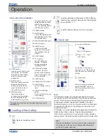
Страница 94: ...MART HEAT DRY CTD SET TEMP ROOMTEMP AUTO AUTO AUTO FAN SPEED POWER 11 12 4 5 COOL button Used to set COOL operation 6 QUIET button 7 n o i t c n u f h c a e f o y a l p s i D status 8 Operation mode display 9 Signal sending end device 10 Signal sending display 11 TEMP display 12 FAN SPEED display Swing up down display swing left right display 13 TIMER ON display TIMER OFF display CLOCK display 14 ...

Страница 95: ...ll be displayed on LCD Please select A without special explanation 19 T E S E R button When the remote controller appears abnormal use a sharp pointed article to press this button to reset the controller normal 20 n o t t u b E R I U Q N I Inquire the external environmental temperature and the operating power of the machine e g when the panel display 01 the operating power is 100W when the panel d...

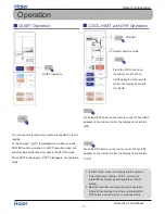
Страница 96: ... silence is needed for rest or reading For each press SOFT is displayed Air conditioner starts POWER function operation In SOFT operation mode fan speed automatically takes low speed of AUTO fan mode Press SOFT button again SOFT disappears the operation stops Operation 1 In DRY mode when room temperature becomes lower than temp setting 35 6 F unit will run intermittently ai LOW speed regardless of...

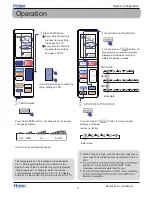
Страница 97: ...utlet if all vertical louvers are adjusted to left or right position for a long time in COOL or DRY mode otherwise condensate water might occur better air circulation The temperature can be increased or decreased by 0 5 ºC while operating the remote control but the display board of the air conditioning unit only displays integral degrees For example when the remote control displays a temperature o...

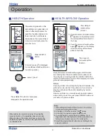
Страница 98: ...green Press HEALTH button for twice press disappears the operation stops For each press is displayed Air conditioner starts health anion function operation Operation When indoor fan motor is running it has healthy process function It s available under any mode When the fan in the indoor unit does not work the health lamp lights up but the anion generator does not release anion HEALTH Operation HEA...

Страница 99: ...s pressed time setting increases or decreases Select your desired TIMER ON Select your desired TIMER OFF For each press is displayed Air conditioner starts POWER function operation In COOL mode fan speed automatically takes high speed of AUTO fan mode Press POWER button again POWER disappears the operation stops POWER Operation TIMER Operation AUTO POWER AM SMART SLEEP LIGHT CHILD LOCK FRESH QUIET...

Страница 100: ... hours temp decrease by 35 6 ºF further After more another 3 hours temp rises by 33 8ºF further The unit will run for further 3 In SMART mode The unit operates in corresponding sleep mode which adapted to the automatically selected operation mode 4 When quiet sleeping function is set to 8 hours the quiet sleeping time can not be adjusted When TIMER function is set the quiet sleeping function can t...

Страница 101: ...er mode you will exit from the smart function The power saving function only works under the cooling heating or dehumidifying mode after the power saving function is set press the sharp mute sleep or smart key to exit the power saving function After the power saving is set the host machine will automatically adjust the setting temperature and automatically control the switch of the compressor whic...

Страница 102: ...peration switch is pressed the Pi sound is heard once which means the start of this operation emergency operation starts the unit will run automatically in the following modes Room temperature Designated temperature Timer mode Fan speed Operation mode Above 75 2 F 75 2 ºF No AUTO COOL Below 75 2ºF 75 2 ºF No AUTO HEAT It is impossible to change the settings of temp and fan speed It is also not pos...

Страница 103: ... label must be adhered in the proximity of the product charging port e g onto the inside of the stop value cover A contains fluorinated greenhouse gases covered by the Kyoto Protocol B factory refrigerant charge of the product see unit name plate C additional refrigerant amount charged in the field D total refrigerant charge E outdoor unit F refrigerant cylinder and manifold for charging IMPORTANT...

Страница 104: ...e than 5cm more than more than10cm more than 15cm more than 60cm A G A F C E D G B Arrangement of piping directions Rear left Left Rear right Right Below G Attention must be paid to the pitch of drain hose X Y X Z Dimensions inches Model x y z Hammer Place where the distance of more than lm from televisions radios wireless apparatuses and fluorescent lamps 3 feet or approximately In the case of fixi...

Страница 105: ...erials of indoor unit 2 Insert the indoor outdoor electric cable from backside of indoor unit and pull it out on the front side then connect them 3 Coat the flaring seal face with refrigerant oil and connect pipes Cover the tubing connection with insulation materials closely and with adhesive tape Fixing the indoor unit body Hang the unit body onto the upper notches of the mounting plate Move the b...

Страница 106: ...ble after installing the indoor unit When connecting the cable before installing the indoor unit Indoor unit Outdoor unit Max Elevation Amax 32 8ft 10m 09k 12k 50ft 15m 18k 24k In case the elevation A is more than 16 4ft 5m oil trap shoud be installed every 5 7m 16 4ft 23ft Max Length Bmax 50ft 15m 09k 12k 83 3ft 25m 18k 24k Insert the cord from the back side of the unit then pull it out on the fr...

Страница 107: ...Run 1 1 2 kg R410A 2 kg 2 1 B C D F E kg A This product contains fluorinated greenhouse gases covered by the Kyoto Protocol Do not vent into the atmosphere Refrigerant type R410A GWP value 1975 GWP global warming potential Please fill in with indelible ink 1 the factory refrigerant charge of the product 2 the additional refrigerant amount charged in the field and 1 2 the total refrigerant charge o...

Страница 108: ...cleaner or flaping them lightly otherwise its performance will be affected the cool and dry conditions For Smart Use of The Air Conditioner Replacement of Air Purifying Filter The white side of the photocatalyst air purifying filter face outside and the black side face the unit The green side of the bacteria killing medium air purifying filter face outside and the white side face the unit Do not u...

Страница 109: ...ITION PROHIBITION Do not start or stop the operation by disconnecting Do not channel the air flow directly at people especially at infants or the aged Do not try to repair or reconstruct by yourself Do not use for the purpose of storage of food art work precise equipment breeding or cultivation CAUTION Take fresh air occasionally especially when gas appliance is running at the same time PROHIBITIO...

Страница 110: ... 250V outdoor broken change it with the type of T 25A 250V The refrigerating circuit is leak proof 1 Applicable ambient temperature range Specifications The machine is adaptive in following situation The power plug and connecting cable acquired the local 2 If the power supply cord is damaged it must be replaced manufacturer qualified person 4 The wiring method should be in line with the local wiri...

Страница 111: ...Seivice diagnosis Domestic air conditioner 9 Dimensional drawings 10 Center of gravity 43 ...

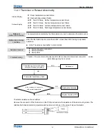
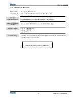
Страница 112: ... Check the power supply Check to make sure that the rated voltage is supplied Check the indoor PCB Check to make sure that the indoor PCB is broken Operation sometimes stops Check the power supply A power failure of 2 to 10 cycles can stop air conditioner operation Equipment operates but does not cool or does not heat only for heat pump Check for faulty operation of the electronic expansion valve ...

Страница 113: ...odel Page 54 F3 4 Communication fault between the IPM and outdoor PCB Page 53 F19 6 Power voltage is too high or low Page 54 F27 7 Compressor is lock rotor or stopped momentary Page 55 F4 8 Overheat protection for Discharge temperature Page 55 e 49 g a P t l u a f r o t o m n a f C D r o o d t u O 9 8 F F21 10 Defrost temperature sensor failure Page 46 F7 11 Suction temperature sensor failure Page...

Страница 114: ... resistance of thermistor using tester The relationship between normal temperature and resistance is shown in the value of indoor thermistor Thermistor resistance check NO YES YES Check the connector connection whether if it loose or misplug Re connect NO Replace the thermistor Replace the indoor PCB Is the resistance is conformity with normal temperature E1 Room temperature sensor failure E2 Heat...

Страница 115: ... the EEPROM are used to determine MCU when the data of EEPROM is error or the EEPROM is damaged ŶFaulty EEPROM data ŶFaulty EEPROM ŶFaulty PCB Caution Be sure to turn off power switch before connect or disconnect connector or parts damage may be occurred Replace the indoor or outdoor mainboard Method of malfunction detection Malfunction detection conditions Troubleshooting Supposed causes 47 ...

Страница 116: ...n the indoor PCB the indoor pcb is damaged and need replace Pull out the terminals on the indoor mainboard and reinsert them Is it ok The fan speed detected by the Hall IC during fan motor running which is used to determine the fan motor operating When there is no fan speed feedback signal within 2 minutes Operation halt due to breaking of wire inside the fan motor Fan motor overheat protection Op...

Страница 117: ... error or the EEPROM is damaged ŶDC fan motor protection dues to the DC fan motor faulty ŶDC fan motor protection dues to faulty PCB Caution Be sure to turn off power switch before connect or disconnect connector or parts damage may be occurred LED1 flash 9 times Outdoor diplay Method of malfunction detection Malfunction detection conditions Troubleshooting Supposed causes 49 ...

Страница 118: ...Measure the voltage between 3 and 6 of the terminal about 0 5v Is it normal NO The motor of the outdoor unit is damaged and needs replacing Measure the voltage between 1 and 3 of the terminal of fan motor on the mainboard about DC310V Measure the voltage between 3 and 4 of the terminal about DC15V Measure the voltage between 5 and 3 of the terminal about 1 6v NO Is it normal The mainboard of the o...

Страница 119: ...unctions are reported after it has run for some time Malfunction unsolved IPM protection is detected by checking the compressor running condition and so on ŶThe system leads to IPM protection due to over current ŶThe compressor faulty leads to IPM protection Ŷcircuit component of IPM is broken and led to IPM protection ŶIPM protection dues to the compressor faulty ŶIPM protection dues to faulty PC...

Страница 120: ...ES NO NO The compressor is started normally but malfunctions are reported after it has run for some time Check the power supply is too low or too high NO Method of malfunction detection Malfunction detection conditions Troubleshooting he current of the compressor is too high when the IPM Module is damaged or the compressor is damaged power supply voltage is too low or too high Supposed causes LED1...

Страница 121: ...ainboard with a new one Replace the outdoor IPM module with a new one YES NO NO YES Malfunction unsolved 1 Pull out and reinsert the terminals 2 Replace connected wire Method of malfunction detection Malfunction detection conditions Troubleshooting Communication is detected by checking the IPM module and the outdoor PCB The outdoor PCB broken leads to communication fault The IPM module broken lead...

Страница 122: ...S NO YES NO The compressor is started normally but malfunctions are reported after it has run for some time Check the power supply is too low or too high NO Method of malfunction detection Malfunction detection conditions Troubleshooting he current of the compressor is too high when the IPM Module is damaged or the compressor is damaged power supply voltage is too low or too high Supposed causes L...

Страница 123: ...ture is below 110 Pull out the exhaust sensor and measure its resistance at standard temperatures according to the resistance temperature table the results deviate much The sensor is damaged Replace the sensor with a new one The outdoor mainboard is damaged and needs be replaced YES NO NO YES Method of malfunction detection Malfunction detection conditions Troubleshooting The Discharge temperature...

Страница 124: ...dust 1 Reconnect the linking cable 2 Replace the linking cable with new one Method of malfunction detection Malfunction detection conditions Troubleshooting Communication is detected by checking the indoor PCB and the outdoor PCB ŶThe outdoor PCB broken leads to communication fault ŶThe indoor PCB broken leads to communication fault ŶCommunication wiring disconnected ŶThe indoor PCB is broken ŶThe...

Страница 125: ...tdoor unit with a multimeter If 230VAC is available but 310DC not the power module is damaged replace it with a new one Test the outdoor power supply 230VAC and 310VDC with a multimeter The outdoor mainboard is damaged replace it with a new one The indoor mainboard is damaged replace it with a new one If the value varies between 0 and 80 VAC the outdoor mainboard is damaged replace it with a new o...

Страница 126: ...imes IPM Module is damaged and needs replacing the Malfunctions exist also the compressor is damaged replace a new one YES NO YES Malfunction unsolved Maybe there is some disturbance Method of malfunction detection Malfunction detection conditions Troubleshooting The position of the compressor rotor can not detected normally when the wiring of compressor is wrong or the connection is poor or the c...

Страница 127: ...s 2 Reinstall the fan Use some tools to measure the pressure of system YES NO YES NO Method of malfunction detection Malfunction detection conditions Troubleshooting High work intense control is activated in the heating mode if the temperature being sensed by the heat exchanger thermistor exceeds the limit Activated when the temperature being sensed by the heat exchanger rises above 65 twice in 30...

Страница 128: ...2 12V 1 1 2 2 3 3 4 4 5 5 6 6 7 7 8 8 9 9 10 10 MODE DIGH DIGL SER SRCK RCK LSTEP_A LSTEP_B LSTEP_C LSTEP_D BUZZ CHECK S_TIME IR SWITCH 5V 5V RST MODE DIG_MODE 1 2 5V 3 R53 R6 R16 R18 R17 R21 5V 1B 1 2B 2 3B 3 4B 4 5B 5 6B 6 7B 7 E 8 COM 9 7C 10 6C 11 5C 12 4C 13 3C 14 2C 15 1C 16 VREF 61 KI0 AN8 P10 49 AN7 P00 50 AN6 P01 51 AN5 P02 52 AN4 P03 53 AN3 P04 54 P62 55 P61 56 CLK1 AN2 P05 57 DA0 AN1 P0...

Страница 129: ...grams Domestic air conditioner Sincere Forever Haier Group Haier Industrial Park No 1 Haier Road 266101 Qingdao China_ Http www haier com Edited by Signed by Approved by Zou Na Yang Xiaodong He shiquan Wu Hongjin ...

Отзывы: