Interfacing to the KE18 I/O Header
Interface of the KE18 to switches and keypads is accomplished by
connection to the 40 pin dual row I/O header. Each of the pins of the
header is connected in parallel with the adjacent pin. This provides 20
individual interface signals, with both the end pins being logic Ground.
The 18 connections are marked “A”-“R” are the KE18 inputs.
18 Input Mode
In the connection of a switch in
the 18 input mode, inputs are
activated by shorting them to
Ground (reference marked “Gnd”).
The example shows one side of
the switch is connected to input
pin “D” and the other is connected
to Ground (“Gnd”), producing the
keystroke “E” when activated (see
KE18 keycode lookup table on
page 6). There are 18 individual
inputs in this mode.
9x9 Matrix Mode
In the 9x9 matrix mode, inputs are
activated by shorting a Column
pin (“A” to “I”) to a Row pin (“J” to
“R”). The example shows input pin
“C” which is a Column, and input
pin “O” which is a Row, producing
the keystroke “X” when activated
(see KE18 keycode lookup table
on page 6). A total of 81 inputs
are available in this mode.
NOTE:
KE18 inputs are for “Dry” contacts only! Never connect
any signal on the KE18 to an external voltage. TTL/CMOS levels
and analog switches are acceptable.
4
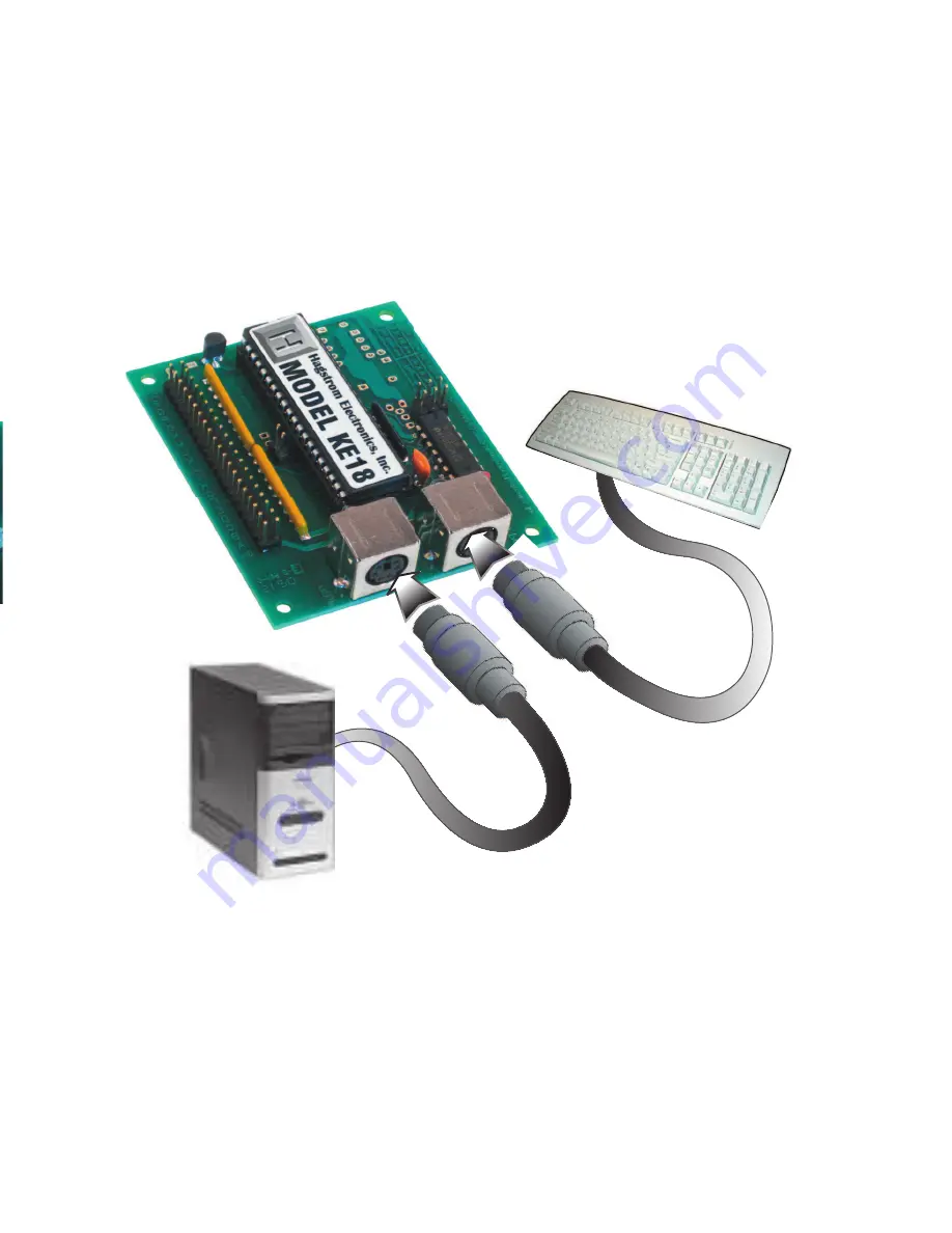
Connection to Computer and Keyboard
There are two miniDIN connectors on your KE18. Each of these
connectors has a different function.
The DIN connector which is marked “To PC” is for interface of the KE18
to the computer. Insert one end of a (male to male) shielded cable
into this port. The other end of the cable connects to the computer’s
keyboard input.
The DIN connector marked “KBD” is for using an external keyboard
with the KE18. Plug the keyboard into this port to use it in addition to
the KE18. Use of the keyboard is optional; a keyboard does not need
to be plugged into this port for the KE18 to operate.
NOTE:
Always perform these connections with the computer’s
power off.
5
KBD
T
O PC
Содержание KE18
Страница 1: ...KE18 PC Keyboard Encoder User Manual...


