


RTN300X · RTN301X
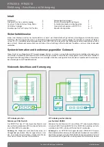
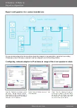
Connection and power supply
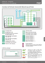
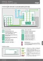
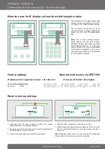
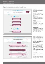
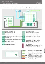
Connecting the call button, name plate lighting and relays
0V
+UB
REL1.1
REL1.2
REL2.1
REL2.2
+24V
ELAN
GND
PE
S3B
GND
+5V
LEDB
Z1
Z2
Z3
Z4
GND
EPOR
T
Ground contact
Reference UB
Operating voltage from external
Power supply (28VDC, 1A)
Relay (NO contact) potential-free,
max. 24V / 2A
Relay (NO contact) potential-free,
max. 24V / 2A
Output 24VDC, 200mA
Not used / no function
Ground for +24V output
Central call button
Ground for central call button
Not used / no function
Not used / no function
Connection for call button 1
Connection for call button 2
Connection for call button 3
Connection for call button 4
Ground for call buttons 1 - 4
Extension port
for the connection of IP display call module
RTN710X
,
IP direct dial keypad module
RTN100X
and IP diode
matrix module
RTN720X
.
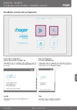
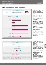
S3B
GND
+5V
LEDB
Z1
Z2
Z3
Z4
GND
0V
+UB
REL1.1
REL1.2
REL2.1
REL2.2
+24V
ELAN
GND
PE
NET
WORK
INPUT
NET
WORK
OUTPUT
EPOR
T
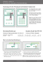
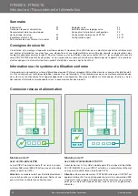
LED status displays
LED2
LED1
IN
OUT
OUT (green)
Continuously on: A device is connected with
the output network port and in operation.
Short flashing signals: Data traffic.
IN (green)
The door speaker module is connected to the
network and in operation. Short flashing sig-
nals: Data traffic.
LED1 (orange)
Continuously on: Door speaker module is con-
nected in a call. Flashing: The factory reset is
complete.
LED2 (red)
Continuously on: The door speaker module is
not registered with the SIP server.
English
Subject to technical changes
13
www.hager.com
Содержание RTN300X
Страница 42: ...42 www hager com...
Страница 43: ...43 www hager com...


