4500 Series Surface Vertical Rod Exit Device
Installation Instructions
Grade 1
I-ED00792
REV 3
Page 5 of 11
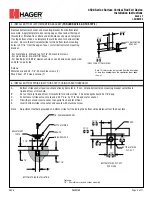
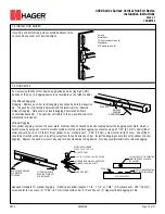
5. INSTALL BOTTOM LATCH MOUNTING BRACKET (FOR LBR DEVICE, GO TO STEP 8)
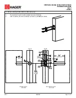
6. INSTALL BOTTOM STRIKE (SKIP THIS STEP IF USING PANIC THRESHOLD)
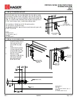
Remove bottom latch cover and mounting bracket from bottom latch
assembly. Apply template to door using edge of door and either top of
threshold or finished floor. Mark and drill holes as shown on template.
If using bottom strike, use template to mark location for bottom strike
anchor. Be sure the vertical centerline for the bottom latch mounting
holes is 2 7/16” from the edge of door. Install bottom latch mounting
bracket.
-For metal doors, drill and tap for 1/4”-20 machine screws.
-For wood doors, pre-drill 1/8” holes.
-For Sex Bolts, drill 5/16” clearance holes on exit device side (push side)
and 3/8” on pull side.
Screws:
Metal door/sex bolt - 1/4”-20 machine screws (1)
Wood door - #12 wood screws (1)
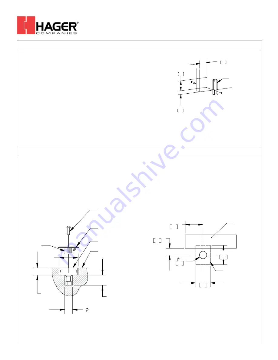
A.
Bottom strike anchor location should already be marked. If not, extend bottom latch mounting bracket centerline to
finished floor or threshold.
B.
Cut out hole in finished floor or threshold for bottom strike. The hole depth should be 7/8” deep.
C.
At bottom of strike cutout, mark and drill 1” dia. by 1 1/4” deep hole for anchor.
D.
Fill with grout and insert anchor to acquire flush and level floor.
E.
Insert bottom strike into anchor and secure with machine screw.
Note:
Adjustment teeth are provided on bottom strike for fine tuning the bottom strike distance from the door face.
1 7/32"
(ONLY FOR BOTTOM STRIKE)
31
3 1/4"
83
2 7/16"
62
LATCH MOUNTING
BRACKET
Note: This dimension is measured from the door edge
or stop face, depending on the application (door edge
shown).
7/8"
1 1/4"
1"
2 1/2"
1/4"-20 MACHINE SCREW
BOTTOM STRIKE
ANCHOR
FINISHED FLOOR
ADJUSTMENT
TEETH
BOTTOM STRIKE INSTALLATION
1 31/32"
50
2 1/2"
64
1"
25
27/32"
21
2 7/16"
62
DOOR
BOTTOM STRIKE
CUT-OUT
BOTTOM STRIKE CUT-OUT
(TOP VIEW)
Fasteners:
1/4” - 20 machine screw and anchor assembly
26490169


