background image


I-LS02110 


www.hagerco.com 

Rev 2, 8/16 

2.


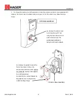
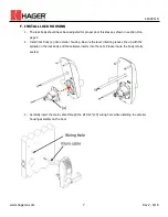
To change the handing to a left handed door, rotate the exterior and interior rose assemblies 180 

degrees. The interior rose is handled in Step 6 on page 10. For the exterior rose, follow the steps 

below: 


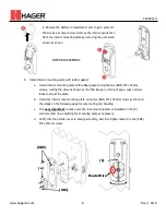
(b). Remove the gasket to access the 

four screws shown. Remove the 

screws below and take out the exterior 
rose assembly, rotating it 180 degrees 

for a left handed door. 

Re-install the four screws followed by 

the gasket & lever to complete the 

outside handing change.


(a). Remove the exterior lever 

by turning the key 90° and 

using the lever removal tool to 

push in the catch pin. The 
exterior lever catch pin is 
facing the left side by default.


EXTERIOR ASSEMBLY 

Exterior Rose Assembly 

Содержание 34K1 series

Страница 1: ...I LS02110 Hager Companies 139 Victor Street St Louis MO 63104 800 325 9995 800 782 0145 FAX www hagerco com Rev 2 8 16 34K1 34K2 SERIES GRADE 1 CYLINDRICAL ELECTRONIC LOCK INSTALLATION INSTRUCTIONS...

Страница 2: ...LS02110 www hagerco com i Rev 2 8 16 Table of Contents A CHECK LIST 1 LOCK COMPONENTS 2 B DOOR PREPARATION 3 C FRAME PREPARATION 4 D ADJUST FOR DOOR THICKNESS 5 E LOCK HANDING 6 F INSTALL LOCK HOUSING...

Страница 3: ...ramming Manual I LS02111 for 34K1 I LS02139 for 34K2 Door Preparation Template T LS02112 Hardware box includes Electrified lock chassis assembly Interior lever Steel ring Exterior rose chassis mountin...

Страница 4: ...Chassis Mntg Plate L Latch Bolt M Screw Post N Exterior Rose Chassis Mntg Plate O Lock Cylinder B DOOR PREPARATION 1 Doors Steel or Wood 2 Door thickness range 1 3 8 35mm 2 51mm 3 Match the Backset o...

Страница 5: ...aking certain that the latch bolt bevel faces direction of closing door see section E for Lock Handing 6 Secure the latch to the door using two 8x3 4 screws SB2 C FRAME PREPARATION 1 Close the door an...

Страница 6: ...otation tabs they should be pointed toward the door 1 Please follow the steps below a Rotate exterior rose mounting plate toward cylindrical chassis b Put the lever release tool into the allocated pos...

Страница 7: ...etermine the hand of your door The product is set up for Right Hand by default INFORMATIONAL PURPOSES ONLY NO ACTION REQUIRED Right Hand Door Left Hand Door Right Hand Reverse Door TOP VIEW Left Hand...

Страница 8: ...sket to access the four screws shown Remove the screws below and take out the exterior rose assembly rotating it 180 degrees for a left handed door Re install the four screws followed by the gasket le...

Страница 9: ...D on page 5 2 Install lock body a into exterior housing Be sure the lever rotation grooves line up with the spindle on the lock body and the tailpiece inserts into the cam Please insure the body is f...

Страница 10: ...as shown in the image on the following page for wire routing and handing c It is very important to make sure the rose mounting plate is installed on the b vertical center line adjusting the mounting...

Страница 11: ...door The lever catch pin should be facing the latch edge of the door 7 Connect the cables to the inside of the e PCB while installing the interior housing Install c the interior housing assembly using...

Страница 12: ...e where lever is rubbing on escutcheon Remove interior lever escutcheon Remove interior spring cage Loosen interior escutcheon mounting plate see Section F Paragraph 5 o Shift plate in directions of b...

Отзывы: