


Page 125
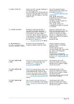
8.3.5.2
Programmable Outputs
PWR BRD OUT 1-6
POWER BOARD OUTPUT1-6 menus typically contain output
settings related to external devices. These relay outputs, located
on the Power and Input/Output Board, are system optional
features.
POWER BOARD OUTPUT1-6 relays can be programmed to a
single output function or to multiple output functions as
described for OUTPUT 1-6 above. The programmed output
function or functions are marked with an asterisk “*” sign in these
menus as in the example for POWER BOARD OUTPUT 2,
which is programmed for STOP, FAULT, WARNING and NOTE
signals below.
In the example below, POWER BOARD OUTPUT 2 is activated
when STOP or FAULT or WARNING or NOTE signal is
triggered.
POWER BOARD OUTPUT 1 is a standard system relay
programmed to STOP and FAULT output functions by default.
In BioTector configuration data download (or in All Data
download), the programmed output functions for each output is
tabulated and marked with asterisk “*” signs for clarity.
PWR BRD OUT 2
DEFAULT STATE
N/E
STOP
*
FAULT
*
WARNING
*
NOTE
*
SAMPLER FILL
………………………
..
………………………
..
……………………..
..
Содержание BioTector B3500C
Страница 17: ...Page 17 Software Menu Diagram...
Страница 44: ...Page 44 Figure 4 BioTector analysis layout typical TIC TOC system...
Страница 46: ...Page 46 Figure 6 BioTector oxygen concentrator layout...
Страница 63: ...Page 63...
Страница 78: ...Page 78 Section 8 Maintenance Menu Maintenance Menu Diagram...
Страница 155: ...Page 155 Section 11 System Replacement and Spare Parts...
Страница 163: ...Page 163 ZK Zero check ZM Manually input zero adjust ZS Zero and Span...


