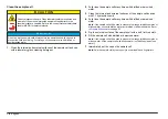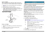
5.
Clean the inside and outside of the plastic parts and tubing with
laboratory detergent and warm water.
Note: At intervals, replace the tubing as contaminants, including
microbiological growths, are difficult to remove from the inside surface of the
tubing.
6.
Air dry the parts after cleaning.
Flow cell maintenance
• Keep all parts of the flow cell assembly clean.
• At intervals, replace all the tubing to make sure that the system is
clean. Keep the tubing as short as possible to minimize air locking and
lag time of sample flow. Locate the instrument as close to the drain as
possible.
Flow cell operation
• Do not use the flow cell for samples that contain large particles that
may collect and stop the sample from flowing.
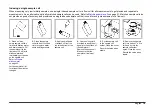
• Slowly put the sample down the interior edge of the inlet reservoir to
prevent mixing of the sample, which can cause air bubbles. Air
bubbles create a false positive interference in a turbidity
measurement.
• If bubbles collect in the flow cell, gently tap the flow cell on a soft
surface to remove the bubbles. If bubbles continue to collect in the
flow cell, put the glass flow cell in liquid detergent for 24 hours and
then rinse fully.
• When measuring many samples of different turbidity, measure the
samples in order of the cleanest (lowest turbidity) to the dirtiest
(highest turbidity) to prevent contamination from one sample to the
next.
• Do not use greater than the recommended maximum sample pressure
of 34 kPa (5 psig).
• Keep the drain tubing below the center line of the instrument. If the
whole 152 cm (60 in.) length of drain tubing is used, make sure that
the end of the drain tubing is at least 46 cm (18 in.) below the center
line of the instrument.
• The flow-cell cover must be in place for the LED light source to
function.
Flow cell storage
• Install the reservoir cover when the system is not in use to prevent
contamination of the system by airborne particles.
• For short-term storage (a few hours), flush the system with distilled or
deionized water and leave the flow cell full of the flush water to
minimize air locks and build up of residue on the parts.
• For long-term storage, disassemble, fully clean and air dry all parts.
Using a manual flow cell
To set the flow rate, increase the height of the collection drain assembly
on the support rod to decrease the flow rate. Make sure that the bottom
of the collection drain assembly is no lower than 7.5 cm (3 in.) above the
support stand base.
To flush the flow cell, lower the collection drain assembly to the support
stand base to flush the flow cell.
Using an automated flow cell
Change the position of the valve-control switch on the flow valve module
to control the flow manually. The valve-control switch has three
positions:
• Continuous Open—The flow valve is open.
• Closed—The flow valve is closed.
• Momentary Open—The flow valve is open while the switch is pushed
down and held to the Momentary Open position. When the switch is
released, the switch goes back to the Closed position and the flow
valve closes.
Set the valve-control switch to the Closed position for automated
operation of the flow valve module. In automated operation, the
instrument controls the flow.
Select static or dynamic mode
In automated operation, the instrument can make flowing (dynamic) or
not flowing (static) sample measurements.
Static mode:
32
English
Содержание 2100AN IS
Страница 1: ...DOC022 53 80206 2100AN IS 05 2014 Edition 4 User Manual...
Страница 2: ......
Страница 51: ......

