


1-15-96
96-8100
169
TABLE OF CONTENTS
TECHNICAL REFERENCE
S E R V I C E M A N U A L
VF-S
ERIES
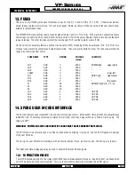
13. FUSES
The servo drive (DRIVER) cards have three fuses on each of the X, Y, Z, and A PCBs (F1, F2, F3). If these fuses are ever
blown, the associated motor will stop. This will only happen if there is a failure of the drive card and the user should never
attempt to replace these fuses.
The POWER PCB contains three ½-amp fuses located at the top right (FU1, FU2, FU3). If the machine is subject to a severe
overvoltage or a lightning strike, these fuses will blow and turn off all of the power. Replace these fuses only with the same
type and ratings. The other two fuses protect the tool changer (FU5) and the operators lamp (FU6).
On the servo drive assembly, there is a printed circuit board (SDIST) containing three one-amp fuses (FU1, FU2, FU3). Two
of these fuses protect the contactor and small transformers. They are never expected to blow. The third fuse protects the
regen load circuit load from shorts.
FUSE NAME
TYPE
RATING
VOLTAGE
LOCATION
(amps)
FU1
AGC
½
250V
POWER pcb,
upper right
FU2
AGC
½
250V
FU3
AGC
½
250V
LAMP
AGC
½
250V
lower left
FU1
AGC
½
250V
SDIST pcb,
right center
FU2
AGC
½
250V
FU3
AGC
5
250V
top center
F1
ABC
20
250V
SDRIVER pcbs (X, Y, Z, A)
F2
ABC
20
250V
F3
ABC
10
250V
FU1
ABC
5
250V
I/O PCB
FU2
ABC
5
250V
I/O PCB
FU3
ABC
5
250V
I/O PCB
FU4
ABC
5
250V
I/O PCB
14. SPARE USER M CODE INTERFACE
The M code interface uses outputs M21-24 and one discrete input circuit. M codes M21 through M24 will activate relays
labled M21-24. These relay contacts are isolated from all other circuits and may switch up to 120V AC at one amp. The
relays are SPDT.
WARNING! POWER CIRCUITS AND INDUCTIVE LOADS MUST HAVE SNUBBER PROTECTION.
The M-FIN circuit is a normally open circuit that is made active by bringing it to ground. The one M-FIN applies to all eight
of the user M codes.
The timing of a user M function must begin with all circuits inactive, that is, all circuits open. The timing is as follows:
The Diagnostic Data display page may be used to observe the state of these signals.
14.1 M FUNCTION RELAYS
The IOPCB contains position for four relays (M21-M24) and all are available to the user. In addition, M21 is already wired
out to P12 at the side of the control cabinet. This is a four-pin DIN connector and includes the M-FIN signal.
Содержание VF-SERIES
Страница 105: ...1 15 96 96 8100 HAAS AUTOMATION INC 105 MECHANICAL SERVICE S E R V I C E M A N U A L VF SERIES acting as a shim ...
Страница 118: ...96 8100 1 15 96 118 MECHANICAL SERVICE HAAS AUTOMATION INC S E R V I C E M A N U A L VF SERIES ...
Страница 119: ...1 15 96 96 8100 HAAS AUTOMATION INC 119 MECHANICAL SERVICE S E R V I C E M A N U A L VF SERIES ...
Страница 148: ...1 15 96 96 8100 145 TABLE OF CONTENTS ELECTRICAL SERVICE VF SERIES S E R V I C E M A N U A L HAAS AUTOMATION INC ...
Страница 149: ...96 8100 1 15 96 146 TECHNICAL REFERENCE SERVICE M A N U A L VF SERIES TECHNICAL REFERENCE SECTION ...
Страница 180: ...1 15 96 96 8100 177 TABLEOFCONTENTS TECHNICAL REFERENCE SERVICE M A N U A L VF SERIES ...
Страница 221: ...96 8100 1 15 96 218 CABLE LOCATIONS HAAS AUTOMATION INC S E R V I C E M A N U A L VF SERIES CABLE LOCATION DIAGRAM ...
Страница 222: ...1 15 96 96 8100 HAAS AUTOMATION INC 219 TABLE OF CONTENTS CABLE LOCATIONS S E R V I C E M A N U A L VF SERIES ...
Страница 233: ...96 8100 1 15 96 230 VF SERIES S E R V I C E M A N U A L ASSEMBLY DRAWINGS CHAPTER 25 ASSEMBLY DRAWINGS ...
Страница 234: ...1 15 96 96 8100 231 TABLE OF CONTENTS VF SERIES S E R V I C E M A N U A L ASSEMBLY DRAWINGS VF 1 BASE ...
Страница 235: ...96 8100 1 15 96 232 VF SERIES S E R V I C E M A N U A L ASSEMBLY DRAWINGS VF 1 COLUMN ...
Страница 236: ...1 15 96 96 8100 233 TABLE OF CONTENTS VF SERIES S E R V I C E M A N U A L ASSEMBLY DRAWINGS VF 1 SADDLE ...
Страница 237: ...96 8100 1 15 96 234 VF SERIES S E R V I C E M A N U A L ASSEMBLY DRAWINGS VF 1 LEADSCREW ...
Страница 238: ...1 15 96 96 8100 235 TABLE OF CONTENTS VF SERIES S E R V I C E M A N U A L ASSEMBLY DRAWINGS VF 3 BASE ...
Страница 239: ...96 8100 1 15 96 236 VF SERIES S E R V I C E M A N U A L ASSEMBLY DRAWINGS VF 3 COLUMN ...
Страница 240: ...1 15 96 96 8100 237 TABLE OF CONTENTS VF SERIES S E R V I C E M A N U A L ASSEMBLY DRAWINGS VF 3 SADDLE ...
Страница 241: ...96 8100 1 15 96 238 VF SERIES S E R V I C E M A N U A L ASSEMBLY DRAWINGS VF 3 LEADSCREW ...
Страница 242: ...1 15 96 96 8100 239 TABLE OF CONTENTS VF SERIES S E R V I C E M A N U A L ASSEMBLY DRAWINGS VF GEARBOX ASSEMBLY ...
Страница 243: ...96 8100 1 15 96 240 VF SERIES S E R V I C E M A N U A L ASSEMBLY DRAWINGS VF SERIES SPINDLE 7 5K 10K VF O SPINDLE 10K ...
Страница 245: ...96 8100 1 15 96 242 VF SERIES S E R V I C E M A N U A L ASSEMBLY DRAWINGS 3 4 2 1 ...


