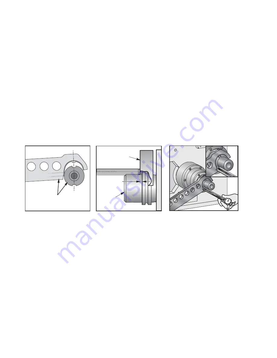
8. Hang a 40 lb (18.2 kg) weight from the pocket side of the arm. Hang the weight from the hole closest to
the pocket. This will preload the arm.
9. Continue to move the arm toward the spindle. Watch the double arm as it approaches the spindle. The
spindle dogs and the slots in the double arm should line up. This will verify Parameter 257 (Spindle
Orient Offset). If the spindle and arm do not line up, reset Parameter 257 as described in the Service
Manual, and continue moving closer until there is a maximum of 1/8" (3.2 mm) gap between the split
tool halves, ensuring that the halves do not touch each other.
10. Check the X and Y alignment of the double arm to the spindle by inserting the alignment dowel through
both halves of the split tool. The dowel should slide freely. If the pin does not slide freely, the direction of
the misalignment may be determined by feeling the "step" between the split tool halves, by using a
steel rule, straight edge, or similar tool.
11. If misalignment is present, read
(ATC Alignment procedure Horizontal)
12. Using T/C Recovery, move the double arm in the forward direction, away from the spindle. Remove both
halves of the split tool.
13. Install a tool holder into the double arm, measure the distance from the front of the double arm to the
front face of the tool holder (see diagram), and record the distance.
Measure the distance from the
surface of the double arm to
the surface of the tool holder
A
6
5
1
2
3
4
5
6
7
8
9
8
1
9
Made in America
Tool Changer
Double Arm
Tool Holder
Measure This
Distance
80
7
0
6
0
90
0
5
0
40
30
2
0
1
0
14. Remove the tool from the double arm. Using T/C Recovery, move the arm in the reverse direction to the
spindle. Continue until the arm rotates to the origin "Home" position. Once the arm is away from the
spindle, insert the same tool holder used in Step 13 into the spindle.
15. Using T/C Recovery, rotate the arm in the forward direction until the arm is very close to the tool holder.
The spring-loaded slide will be depressed as the arm nears the tool holder, but be sure that the arm is
not touching the tool holder itself.
16. Using a caliper, measure between the same two surfaces described in Step 13. The measurement
should be the same, +/-.010" (.254 mm). Be sure that you are measuring the distance between the
double arm and the tool holder, not the spring-loaded slide and the tool holder. If adjustment is required,
refer to "Setting Parameter 64" in the Service Manual.
17. If no changes are needed, complete Tool Change Recovery.
18. Note that the same end of the double arm must be used for the caliper measurement. The two ends
may have different readings. This is normal and will not affect operation.
19. Load tools (maximum 30 lbs (13.6 kg) each) into the machine, and perform tool changes to verify
proper operation. Caution: Protect the Z-axis way cover (closest to the column) in case a tool is
dropped from the spindle or tool changer arm. The tool changer should be operated at 100% rapid
speed, otherwise tool changer motion may jerk or be sluggish.
© Copyright 2015 by Haas Automation, Inc. No unauthorized reproduction.
Page 6 of 6


