background image


2-5 

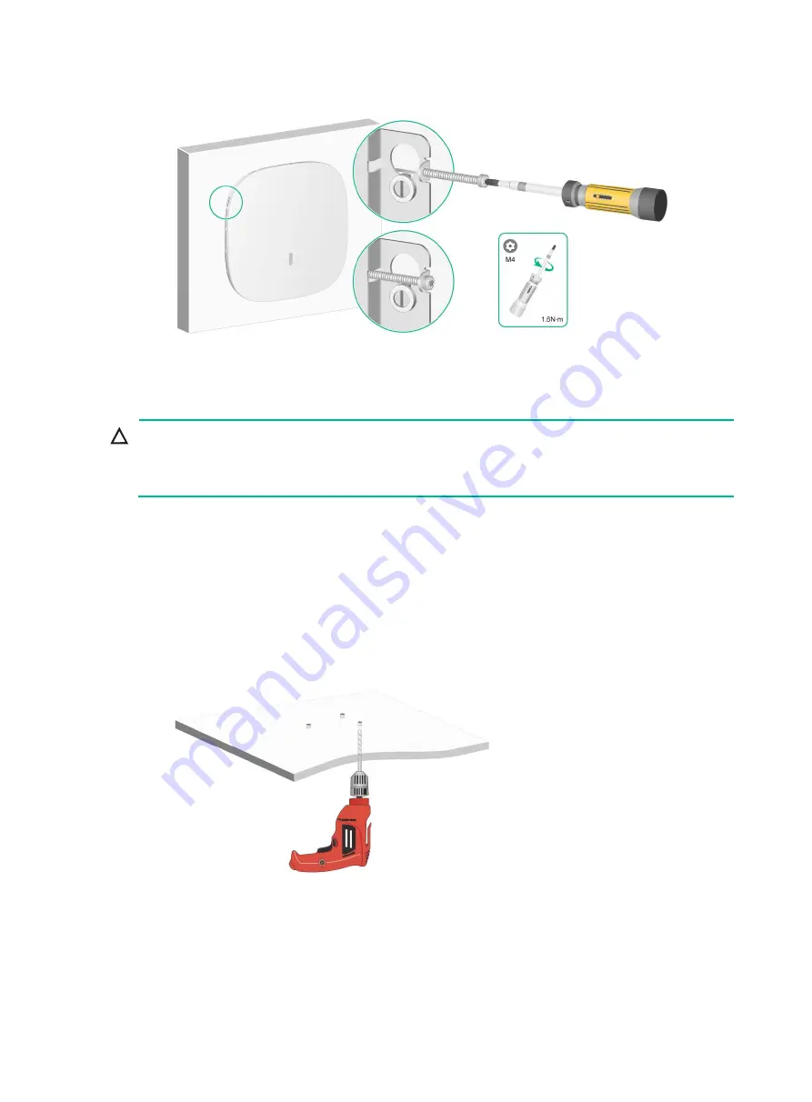
Figure 2-9 Fastening the M3 × 23.5 security screw 


Mounting the AP on a ceiling 


CAUTION: 

The ceiling for installing the AP must be less than 18 mm (0.71 in) in thickness, and can bear a load 
of 5 kg (11.02 lb). If you must install the AP on a ceiling not strong enough, use boards to reinforce 
the ceiling. 


The installation method for the M3 × 23.5 security screw is similar when the AP is mounted on the 
wall and on the ceiling. 

To mount the AP on a ceiling: 

1. 

Remove the ceiling tile. 

2. 

Place the mounting bracket against the ceiling tile and mark the installation holes on the ceiling 
tile. Drill three holes with a diameter of 6 mm (0.24 in) at the marked positions, as shown in 

Figure 2-10

. 

Figure 2-10 Drilling holes in the ceiling tile 


3. 

Thread the pan-head screws through the installation holes in the mounting bracket and into the 
holes in the ceiling tile. Fasten washers and nuts at the other side of the ceiling to secure the 
mounting bracket to the ceiling, as shown i

Figure 2-11

. 

Содержание WA6320

Страница 1: ...H3C WA6320 Access Point Installation Guide New H3C Technologies Co Ltd http www h3c com Document version 5W100 20200224 ...

Страница 2: ...respective owners Notice The information in this document is subject to change without notice All contents in this document including statements information and recommendations are believed to be accurate but they are presented without warranty of any kind express or implied H3C shall not be liable for technical or editorial errors or omissions contained herein Environmental protection This produc...

Страница 3: ...ts that are optional x y Braces enclose a set of required syntax choices separated by vertical bars from which you select one x y Square brackets enclose a set of optional syntax choices separated by vertical bars from which you select one or none x y Asterisk marked braces enclose a set of required syntax choices separated by vertical bars from which you select a minimum of one x y Asterisk marke...

Страница 4: ...as a Layer 2 or Layer 3 switch or a router that supports Layer 2 forwarding and other Layer 2 features Represents an access controller a unified wired WLAN module or the access controller engine on a unified wired WLAN switch Represents an access point Represents a wireless terminator unit Represents a wireless terminator Represents a mesh access point Represents omnidirectional signals Represents...

Страница 5: ...Documentation feedback You can e mail your comments about product documentation to info h3c com We appreciate your comments ...

Страница 6: ...ks 2 1 Determining the installation position 2 2 Mounting the AP 2 2 Mounting bracket 2 2 Mounting the AP on a wall 2 2 Mounting the AP on a ceiling 2 5 Connecting the AP to a power source 2 7 Connecting a PoE power source 2 7 Connecting a local power source 2 7 Check after power on 2 8 Connecting the AP to the network 2 8 3 Appendix A Technical specifications 3 1 4 Appendix B Ports and LEDs 4 1 P...

Страница 7: ... a dry and flat location and take anti slip measures Keep the AP clean and dust free Do not place the AP in a moist area and avoid liquid intrusion Keep the AP and installation tools away from walkways Site preparation Before installing the AP examine the installation site and make sure the AP will operate in a favorable environment Make sure the temperature and humidity at the installation site m...

Страница 8: ...1 2 Installation tools When installing the AP you might need the following tools Prepare the installation tools yourself as required Figure 1 2 Installation tools ...

Страница 9: ...e the LEDs to verify that the AP is operating correctly For information about AP LEDs see LEDs Record the MAC address and serial number at the rear of the AP for future use Make sure you have completed cabling at the installation site Start Complete pre installation tasks Determine the installation position Mount the AP On a wall On a ceiling Connect the AP to the power source Connect the AP to th...

Страница 10: ...the AP IMPORTANT Before mounting the AP on a wall or ceiling connect cables to the AP Install an M3 23 5 security screw as required The AP can be installed only indoors You can mount the AP on a wall or a ceiling Mounting bracket Figure 2 2 Mounting bracket 1 Installation hole for securing the mounting bracket to a wall or ceiling point A 2 T rail installation hole reserved Point B 3 Auxiliary hol...

Страница 11: ...2 4 Figure 2 4 Drilling holes in the wall 3 Insert a screw anchor into each hole and tap the screw anchor with a rubber hammer until it is all flush with the wall surface as shown in Figure 2 5 Figure 2 5 Hammering the screw anchor into the wall 4 Thread the M3 23 5 security screw through the security hole in the mounting bracket Make sure the screw does not block the keyhole slot ...

Страница 12: ...ng bracket to the wall as shown in Figure 2 7 Figure 2 7 Attaching the mounting bracket to the wall 6 Position the four pegs at the AP rear into the keyhole slots in the mounting bracket and then slide the AP down until it clicks into place as shown in Figure 2 8 Figure 2 8 Attaching the AP to the mounting bracket 7 Use a security Torx screwdriver to fasten the M3 23 5 security screw ...

Страница 13: ...d on the wall and on the ceiling To mount the AP on a ceiling 1 Remove the ceiling tile 2 Place the mounting bracket against the ceiling tile and mark the installation holes on the ceiling tile Drill three holes with a diameter of 6 mm 0 24 in at the marked positions as shown in Figure 2 10 Figure 2 10 Drilling holes in the ceiling tile 3 Thread the pan head screws through the installation holes i...

Страница 14: ... and do not tighten the cable tie Then connect a cable to the AP adjust the cable length and then tighten the cable tie to secure the cable to the AP No cable tie is provided with the AP Prepare one yourself as required Figure 2 12 Securing a cable 5 Position the four pegs at the AP rear into the keyhole slots in the mounting bracket and slide the AP until it clicks into place as shown in Figure 2...

Страница 15: ...out routing to the outside plant To power the AP through PoE use an Ethernet cable to connect an Ethernet port on a PoE switch to the GE PoE port on the AP Figure 2 14 Powering the AP through PoE Connecting a local power source You can use an AC DC power adapter to connect the AP to a local power source No power adapter is provided with the AP Prepare one yourself as required Table 2 1 describes t...

Страница 16: ...as been connected to the network Sysname display wlan ap all Total number of APs 1 Total number of connected APs 1 Total number of connected manual APs 1 Total number of connected auto APs 0 Total number of connected common APs 1 Total number of connected WTUs 0 Total number of inside APs 0 Maximum supported APs 3072 Remaining APs 3071 Total AP licenses 128 Remaining AP licenses 127 AP information...

Страница 17: ...cations Table 3 1 Technical specifications Item Specification Dimensions H W D 185 185 33 mm 7 28 7 28 1 30 in Weight 423 g 14 92 oz Antenna Built in antenna Power consumption 12 42 W Protocol 802 11b g a n ac ax 802 3af Dual frequency ...

Страница 18: ...iption Console port RS EIA 232 Used by technical personnel only for device configuration and management 10 100 1000M Ethernet copper port GE PoE IEEE802 3 IEEE802 3u IEEE802 3af Used for connecting the AP to an uplink device for Internet or MAN access It can also receive PoE power from the uplink device Power port 54 V N A Used for receiving 54 VDC power from a local power source Reset button N A ...

Страница 19: ...hernet interfaces are down and no mesh links are established Green Steady on The AP has registered to an AC but does not have any associated clients Flashing at 0 5 Hz The AP has started up but has not registered to any AC Flashing at 1 Hz Only the 2 4G radio has associated clients Flashing at 2 Hz The AP is upgrading the image Blue Flashing at 1 Hz Only the 5G radio has associated clients Alterna...

Отзывы: