background image


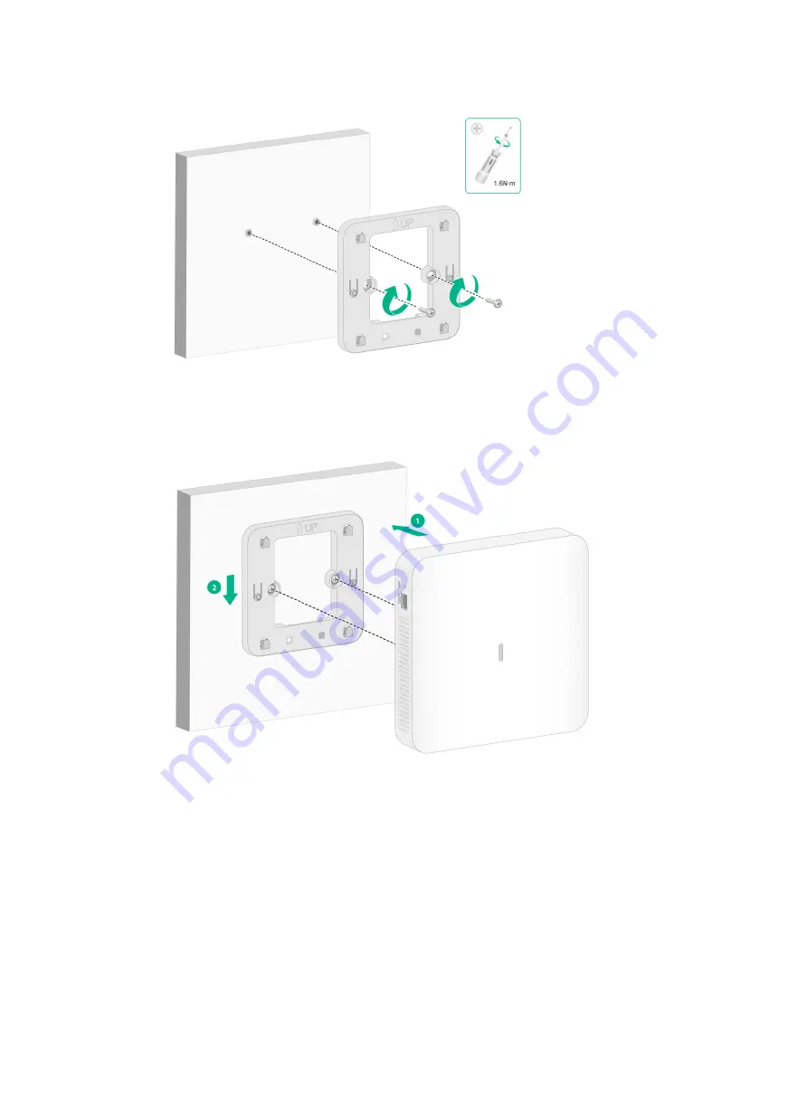
Figure 8 Attaching the mounting bracket to the wall 


5. 

Position the keyhole slots in the AP rear on the four pegs of the mounting bracket and then 
slide the AP down until it sits securely on the pegs, as shown i

Figure 9

. 

Figure 9 Attaching the AP to the mounting bracket 


Mounting the AP on a Junction box 

1. 

Use the provided M4 × 30 mm pan-head screws to attach the mounting bracket to the Junction 
box. 

Содержание WA6020

Страница 1: ...H3C WA6020 Access Point Installation Guide New H3C Technologies Co Ltd http www h3c com Document version 6W100 20230908 ...

Страница 2: ...respective owners Notice The information in this document is subject to change without notice All contents in this document including statements information and recommendations are believed to be accurate but they are presented without warranty of any kind express or implied H3C shall not be liable for technical or editorial errors or omissions contained herein Environmental protection This produc...

Страница 3: ...ts that are optional x y Braces enclose a set of required syntax choices separated by vertical bars from which you select one x y Square brackets enclose a set of optional syntax choices separated by vertical bars from which you select one or none x y Asterisk marked braces enclose a set of required syntax choices separated by vertical bars from which you select a minimum of one x y Asterisk marke...

Страница 4: ...as a Layer 2 or Layer 3 switch or a router that supports Layer 2 forwarding and other Layer 2 features Represents an access controller a unified wired WLAN module or the access controller engine on a unified wired WLAN switch Represents an access point Represents a wireless terminator unit Represents a wireless terminator Represents a mesh access point Represents omnidirectional signals Represents...

Страница 5: ...Documentation feedback You can e mail your comments about product documentation to info h3c com We appreciate your comments ...

Страница 6: ...ower source 6 Connecting a PoE power source 8 Check after power on 8 Connecting the AP to the network 8 Verifying that the AP has been connected to the network when it operates in fit mode 8 Verifying that the AP has been connected to the network when it operates in cloud mode 9 Accessing the AP 1 Logging in to the AP from the console port 1 Connecting the AP to a configuration terminal from the c...

Страница 7: ...before installing the AP Note that the recommendations do not cover every possible hazardous condition To avoid bodily injury and device damage take adequate safety measures Place the AP in a dry and flat location and take anti slip measures Keep the AP clean and dust free Do not place the AP in a moist area and avoid liquid intrusion Keep the AP and installation tools away from walkways Site prep...

Страница 8: ...on accessories Figure 1 Accessories provided with the AP Installation tools When installing the AP you might need the following tools Prepare the installation tools yourself as required Figure 2 Installation tools ...

Страница 9: ...d ports Record the MAC address and serial number at the rear of the AP for future use Make sure you have completed cabling at the installation site Use Cat 5e or above network cables For information about the supported interface rates see Appendix B LEDs and ports The AP is typically installed on a high position As a best practice access and configure the AP before installing it If a cable is rout...

Страница 10: ... between the AP and other radiant resources for example wireless base station antennas The AP does not hinder people s daily work and life The place is not water seeping water soaking and condensing Mounting the AP The AP can be installed only indoors You can mount the AP on a wall a Junction box or a ceiling Mounting bracket Figure 4 Mounting bracket Mounting the AP on a wall 1 Place the mounting...

Страница 11: ...6 Drilling holes in the wall 3 Use a rubber hammer to tap a screw anchor into each hole until it is all flush with the wall surface as shown in Figure 7 Figure 7 Hammering the screw anchor into the wall 4 Insert the screws through the installation holes in the mounting bracket into the holes in the wall Fasten the screws to secure the mounting bracket to the wall as shown in Figure 8 ...

Страница 12: ...n the four pegs of the mounting bracket and then slide the AP down until it sits securely on the pegs as shown in Figure 9 Figure 9 Attaching the AP to the mounting bracket Mounting the AP on a Junction box 1 Use the provided M4 30 mm pan head screws to attach the mounting bracket to the Junction box ...

Страница 13: ...ing not strong enough use boards to reinforce the ceiling To mount the AP on a ceiling 1 Remove the ceiling tile 2 Place the mounting bracket against the ceiling tile and mark the installation holes on the ceiling tile Drill two holes with a diameter of 6 mm 0 24 in at the marked positions as shown in Figure 11 Figure 11 Drilling holes in the ceiling tile 3 Thread the M4 30 mm pan head screws thro...

Страница 14: ...from falling off Connecting the AP to a power source You can supply power to the AP by using a local power source or through 802 3af compliant PoE as required Before powering the AP make sure the local power source or the 802 3af compliant power sourcing equipment PSE is grounded reliably Connecting a local power source Connecting a local power source by using a power adapter You can use an AC DC ...

Страница 15: ...e 1 Insert a flat head screwdriver straight into a square shaped hole in the terminal block This will open the round shaped hole above the square shaped hole 2 Hold the screwdriver and insert one wire into the round shaped hole in the terminal block Identify the positive and negative feed positions The wiring sequence is positive to positive and negative to negative 3 Take out the flat head screwd...

Страница 16: ...ter power on Examine the LEDs on the AP after you power on it to verify that the AP is operating correctly For more information about the LEDs see Appendix B LEDs and ports Connecting the AP to the network Verifying that the AP has been connected to the network when it operates in fit mode When the AP operates in fit mode all AP settings are configured on the AC To verify the network connectivity ...

Страница 17: ...ing AP licenses 127 AP information State I Idle J Join JA JoinAck IL ImageLoad C Config DC DataCheck R Run M Master B Backup AP name AP ID State Model Serial ID ap1 1 R M WA6020 219801A3L58224E00031 Verifying that the AP has been connected to the network when it operates in cloud mode When the AP operates in cloud mode use a wireless terminal to search for and access the wireless service provided ...

Страница 18: ...AP first disconnect the AP end If the PC does not have an RS 232 port but a USB port use a USB to RS 232 converter to connect the USB port to the console cable and install the driver on the PC To connect the AP to a configuration terminal from the console port 1 Connect the DB 9 connector of the console cable to the serial port on the configuration terminal for example a PC 2 Connect the RJ 45 con...

Страница 19: ... Make sure the PC obtains an IP address dynamically When the AP operates in cloud mode it obtains the IP address of VLAN 1 dynamically by default Some Intel wireless adapters do not support 802 11ax For clients to detect Wi Fi 6 networks upgrade the driver for the wireless adapter to the most recent version For more information see the official statement of Intel To log in to the AP through a wire...

Страница 20: ...ersion For more information see the official statement of Intel To log in to the AP through a wireless connection 1 Enable WLAN on the configuration terminal and access WLAN H3C_xxxxxx where xxxxxx is the last six bits of the AP s MAC address 2 Visit http wlan h3c com from a browser and then press Enter 3 Enter the default username and password For security purposes change the password as prompted...

Страница 21: ...d install Cloudnet App Int from Google Play Store Logging in to the Cloudnet platform To manage the AP from the Cloudnet platform make sure the AP uses an IP address that can reach the external network To log in to the Cloudnet platform 1 Open Cloudnet App Int or visit https oasiscloudnet h3c com from a browser 2 Enter the username and password After login you can add the AP to the platform and ma...

Страница 22: ...i Contents Appendix A AP view and technical specifications 1 AP view 1 Technical specifications 1 ...

Страница 23: ...cifications for the WA6020 Item Description Dimensions H W D 32 180 180 mm 1 26 7 09 7 09 in mounting bracket excluded System power consumption 13 W Antenna Built in antenna 2 4 G 3 dBi gain 5 G 4 dBi gain Power supply DC power supply PoE power supply complies with IEEE802 3af Protocol IEEE802 11a b g n ac ax IEEE802 3af ...

Страница 24: ...i Contents Appendix B LEDs and ports 1 LEDs and buttons 1 Ports 2 ...

Страница 25: ...tions cloud mode LED status Description Off No power is present or the LED has been turned off Yellow Steady on The AP is initializing or an initialization exception has occurred Flashing twice per second The Ethernet interfaces are down and no mesh links are established Green Steady on The AP is in standby state and has connected to the Cloudnet platform but does not have any associated clients F...

Страница 26: ...perating mode to cloud NOTE If you release the button the AP will restart for the new mode to take effect Ports The AP provides the following ports One console port One GE PoE port One power port The AP also has a reset button and a security slot The security slot is 7 3 mm 0 28 0 12 in in size Figure 1 Ports on the AP 1 1 Security slot 2 GE PoE port 3 Power port Figure 2 Ports on the AP 2 1 Reset...

Страница 27: ...02 3af 10 100 1000M Ethernet copper port used for connecting the AP to an uplink device for Internet or MAN access It can also receive PoE power from the uplink device When the AP operates in fit mode the port is represented by interface number GE1 0 1 in the MAP file and gigabitethernet 1 for configuration on the AC 54V DC N A Power port used for receiving 54 VDC power from a local power source ...

Отзывы: