background image

15 

Connecting the power cord 

Guidelines 


WARNING! 

To avoid damage to the equipment or even bodily injury, use the power cord that ships with the 
server. 


Before connecting the power cord, make sure the server and components are installed correctly.  

Procedure 

1. 

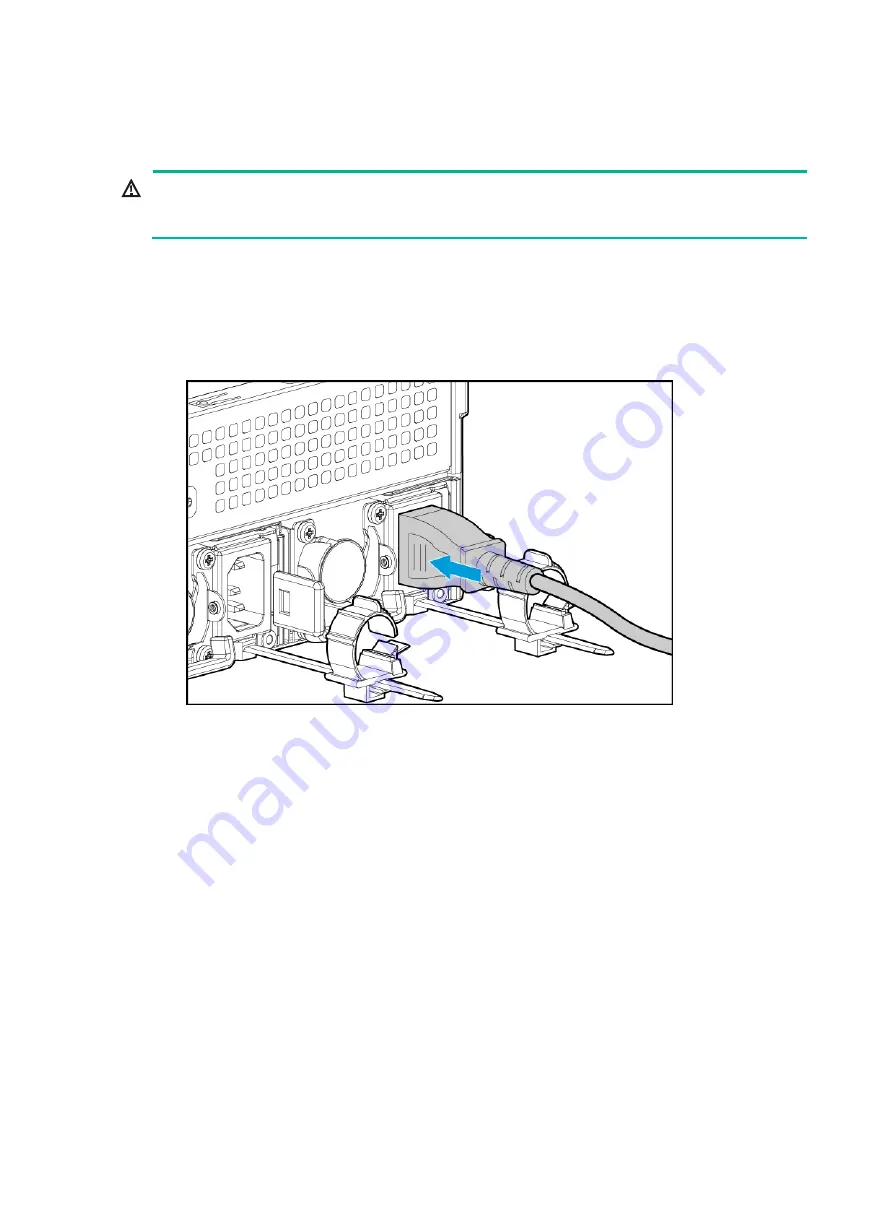
Insert the power cord plug into the power receptacle of a power supply at the rear panel, as 
shown i

Figure 8

. 

Figure 8 Connecting the power cord 


2. 

Connect the other end of the power cord to the power source, for example, the power strip on 
the rack. 

3. 

Secure the power cord to avoid unexpected disconnection of the power cord. 

a. 

If the cable clamp is positioned too near the power cord that it blocks the power cord plug 
connection, press down the tab on the cable mount and slide the clip backward. 

Содержание UniServer R6900 G5

Страница 1: ...nstalling rails 11 Rack mounting the server 11 Installing cable management brackets 12 Connecting external cables 12 Cabling guidelines 12 Connecting a mouse keyboard and monitor 12 Connecting an Ethe...

Страница 2: ...drive 34 Verifying the replacement 34 Replacing an NVMe drive 34 Guidelines 34 Prerequisites 34 Removing an NVMe drive 35 Installing an NVMe drive 35 Verifying the replacement 35 Replacing the system...

Страница 3: ...Installing a SATA M 2 SSD expander module 52 Replacing an SD card 52 Guidelines 52 Prerequisites 52 Removing an SD card 52 Installing an SD card 52 Replacing a dual SD card extended module 53 Prerequi...

Страница 4: ...ive configurations and cabling guide 63 Connecting power cords 66 Connecting AUX signal cables 67 Connecting data cables 69 Connecting supercapacitor extension cables 75 Connecting the GPU power cord...

Страница 5: ...with the field servicing forbidden sign in any circumstances The RJ 45 ports on the server can be used only for Ethernet connections WARNING To avoid electrical shocks fire or damage to the equipment...

Страница 6: ...on standby button on the front panel the power supplies continue to supply power to some circuits in the server To remove all power for servicing safety you must first press the button wait for the s...

Страница 7: ...emoving them from their antistatic bags Avoid touching pins leads or circuitry Grounding methods to prevent electrostatic discharge The following are grounding methods that you can use to prevent elec...

Страница 8: ...t need to replace the battery When you replace the battery follow these safety guidelines Do not attempt to recharge the battery Do not expose the battery to a temperature higher than 60 C 140 F Do no...

Страница 9: ...limits for different rack depth see Table 2 Table 2 Installation limits for different rack depths Rack depth Installation limits 1000 mm 39 37 in The H3C cable management arm CMA is not supported A c...

Страница 10: ...e front rack door 3 780 mm 30 71 in between the front rack posts and the rear of the chassis including power supply handles at the server rear not shown in the figure 4 800 mm 31 50 in server depth in...

Страница 11: ...t room height requirements To ensure correct operation of the server make sure the equipment room height meets the requirements as described in Appendix A Server specifications Cleanliness requirement...

Страница 12: ...dia As a best practice do not store an HDD for 6 months or more without powering on and using it As a best practice do not store an SSD M 2 SSD or SD card for 3 months or more without powering on and...

Страница 13: ...nut insertion extraction tool Inserts or extracts the cage nuts in rack posts Diagonal pliers Clips insulating sleeves Tape measure Measures distance Multimeter Measures resistance and voltage ESD wri...

Страница 14: ...cts the serial connector on the server to a monitor for troubleshooting Monitor Displays the output from the server Temperature humidity meter Displays current temperature and humidity Oscilloscope Di...

Страница 15: ...more information about how to slide the server into the rack see the document shipped with the rails Figure 3 Rack mounting the server 2 Secure the server a Push the server until the multifunctional...

Страница 16: ...es block the inlet or outlet air vents of the server To easily identify ports and connect disconnect cables make sure the cables do not cross Label the cables for easy identification of the cables Wra...

Страница 17: ...cable to the VGA connector on the monitor and fasten the screws on the plug 3 Connect the mouse and keyboard For a USB mouse and keyboard directly connect the USB connectors of the mouse and keyboard...

Страница 18: ...ctivity of the cable by using a link tester If you are replacing the Ethernet cable make sure the new cable is the same type or compatible with the old cable 3 Label the Ethernet cable by filling in t...

Страница 19: ...d plug into the power receptacle of a power supply at the rear panel as shown in Figure 8 Figure 8 Connecting the power cord 2 Connect the other end of the power cord to the power source for example t...

Страница 20: ...power cord through the opening in the cable clamp and then close the cable clamp as shown by callouts 1 2 3 and 4 in Figure 10 Figure 10 Securing the AC power cord c Slide the cable clamp forward unt...

Страница 21: ...ment secure cables to left slide rails When multiple cable straps are used in the same rack stagger the strap location so that the straps are adjacent to each other when viewed from top to bottom This...

Страница 22: ...ver 3 Extend the server from the rack a Open the latches of the multifunctional rack mount ears as shown by callout 1 in Figure 13 b Loosen the captive screws inside the multifunctional rack mount ear...

Страница 23: ...rom steady amber to flashing green and then to steady green For information about the position of the system power LED see LEDs and buttons Powering on the server from the HDM Web interface 1 Log in t...

Страница 24: ...ng off the server from its operating system 1 Connect a monitor mouse and keyboard to the server 2 Shut down the operating system of the server 3 Disconnect all power cords from the server Powering of...

Страница 25: ...om the remote console interface 1 Log in to HDM For information about how to log in to HDM see the firmware update guide for the server 2 Log in to a remote console and then power off the server For i...

Страница 26: ...on the server 1 Power on the server For information about the procedures see Powering on the server 2 Verify that the health LED on the front panel is steady green which indicates that the system is o...

Страница 27: ...er password for the BIOS setup utility you must enter the administrator password or user password each time you access the BIOS setup utility To obtain administrator privileges enter the administrator...

Страница 28: ...tall a hardware driver see the operating system installation guide for the server Updating firmware IMPORTANT Verify the hardware and software compatibility before firmware upgrade For information abo...

Страница 29: ...r Installing the access panel 1 Open the locking lever of the access panel Then press the button on the locking lever and lift the locking lever 2 Install the access panel a Place the access panel on...

Страница 30: ...Do not wear any conductive objects such as jewelry or watches Removing and installing a blank Install blanks over the empty slots if the following modules are not present and remove blanks before you...

Страница 31: ...e riser card Remove an OCP network adapter blank Pinching the handle on the OCP network adapter blank pull the blank out Install an OCP network adapter blank Insert the OCP network adapter blank in to...

Страница 32: ...nd Figure 17 Memory Rank Sparing A minimum of 2 ranks per channel DIMM installation schemes If two processors are present see Figure 15 If four processors are present see Figure 16 and Figure 17 NOTE...

Страница 33: ...conductive objects such as jewelry or watches When you replace a component examine the slot and connector for damages Make sure the pins are not damaged bent for example and do not contain any foreig...

Страница 34: ...nal Enter the BIOS to change the memory mode if necessary For more information see the BIOS user guide of the server Verifying the replacement Use one of the following methods to verify that the DIMM...

Страница 35: ...ste the barcode label shipped with the processor to the side of the heatsink to cover the original barcode label on the heatsink This ensures that H3C will provide the warranty service for the process...

Страница 36: ...et CAUTION To avoid damage to the processor always hold the processor by its edges Never touch the gold contacts on the processor bottom a Align the small triangle on the processor with the alignment...

Страница 37: ...owest capacity is used across all drives in the RAID If one drive is used by several logical drives RAID performance might be affected and maintenance complexities will increase If the installed drive...

Страница 38: ...BIOS For more information see the storage controller user guide for the server Access the CLI or GUI of the server Observe the drive LEDs to verify that the drive is operating correctly For more infor...

Страница 39: ...rmation see Powering off the server 2 Remove the drive Press the button on the drive panel to release the locking lever and then hold the locking lever and pull the drive out of the slot 3 Remove the...

Страница 40: ...then lift the fan cage out of the chassis 8 Remove all riser cards installed on the server 9 Remove the riser card cage 10 Remove the processor mezzanine board 11 Disconnect all cables connected to t...

Страница 41: ...8 Connect the power cord For more information see Connecting the power cord 19 Power on the server For more information see Powering on the server Replacing the processor mezzanine board WARNING To av...

Страница 42: ...s b Press and close the locking levers at both sides till they click into place c Install the removed GPU support brackets Slide a GPU support bracket along the slot until the standout of the GPU fits...

Страница 43: ...nds press the blue tabs and lift the air baffle out of the chassis 5 Remove the processor mezzanine board 6 Remove the midplane Remove all the screws that secure the midplane to the server and then pu...

Страница 44: ...lane 7 Remove the drive backplane Loosen the captive screws that secure the backplane and then lift the backplane out of the chassis Installing a drive backplane 1 Install a drive backplane Place the...

Страница 45: ...g the guide rails and then close the retaining latch 9 Install the riser card installed with the PCIe module a Unlock the riser card Slide the locking tab to release the locking lever b Inset the rise...

Страница 46: ...ore information see Removing the server from a rack 3 Remove the access panel For more information see Removing the access panel 4 Remove the chassis air baffle 5 Disconnect all cables that hinder the...

Страница 47: ...become Abnormal_status code You can check the status code to identify the exception For more information see HDM online help For an LSI storage controller the status of the flash card of the power fai...

Страница 48: ...ame model make sure the following configurations remain the same after replacement Storage controller operating mode Storage controller firmware version BIOS boot mode First boot option in Legacy mode...

Страница 49: ...lash card on the power fail safeguard module a Install the internal threaded studs supplied with the power fail safeguard module on the standard storage controller b Install the flash card on the stan...

Страница 50: ...ine the slot and connector for damages Make sure the pins are not damaged bent for example and do not contain any foreign objects Installing an OCP network adapter 1 Power off the server For more info...

Страница 51: ...ove the access panel For more information see Removing the access panel 5 Disconnect all cables that hinder the replacement if any 6 Remove the riser card where the PCIe network adapter resides For mo...

Страница 52: ...move it from the chassis Installing an OCP adapter 1 Install the OCP adapter a Install the OCP adapter onto the OCP adapter connector b Fasten the screws to secure the OCP adapter 2 Install the system...

Страница 53: ...of them on the same server To install multiple dual slot wide modules a maximum of three install them in PCIe slots in the following order slots 2 8 and then 14 To install multiple single slot wide mo...

Страница 54: ...id bodily injury from hot surfaces allow the server and its internal modules to cool before touching them An M 2 expander module is required for SATA M 2 SSDs You can install the expander module in a...

Страница 55: ...ting the server 6 Connect the power cord For more information see Connecting the power cord 7 Power on the server For more information see Powering on the server Replacing a SATA M 2 SSD expander modu...

Страница 56: ...server Replacing an SD card Guidelines Two SD cards installed on a dual SD extended module create a RAID 1 volume by default To avoid storage space waste install two SD cards with the same capacity Pr...

Страница 57: ...2 Remove the server from the rack For more information see Removing the server from a rack 3 Remove the access panel For more information see Removing the access panel 4 Remove the riser card cage th...

Страница 58: ...ere the NVMe SSD expander module resides a Disconnect cables from the NVMe SSD expander module b Remove the riser card For more information see Removing a riser card and a PCIe module 5 Remove the NVM...

Страница 59: ...ress the clip of the LCD smart management module and pull the module out from the slot Install the LCD smart management module 1 Install the LCD smart management module a Connect one end of the LCD mo...

Страница 60: ...ser can perform the tasks When replacing the system board do not remove the TCM or TPM from the system board H3C will provide a TCM or TPM with a spare system board for the replacement Any attempt to...

Страница 61: ...ccess panel For more information see Installing the access panel 10 Rack mount the server For more information see Rack mounting the server 11 Connect the power cord For more information see Connectin...

Страница 62: ...e information see Removing the server from a rack 3 Remove the access panel For more information see Removing the access panel 4 Remove the processor mezzanine board if any 5 Remove the NVMe VROC modu...

Страница 63: ...s panel 4 Remove the system battery Pinch the system battery by its top edge and lift the battery out of the battery holder slowly NOTE For environment protection purposes dispose of the used up syste...

Страница 64: ...onnecting the power cord 5 Power on the server if the server has been powered off For more information see Powering on the server Replacing a power supply The power supplies are hot swappable Guidelin...

Страница 65: ...power supply and then pull the connector out 5 Remove the power supply Holding the power supply by its handle and pressing the retaining latch with your thumb pull the power supply slowly out of the...

Страница 66: ...ing a chassis ear 1 Install a chassis ear Attach the chassis ear to the corresponding side of the server and use screws to secure the chassis ear into place 2 Install the front I O component cable ass...

Страница 67: ...abling solutions for drives including the connections between the cables and connectors see Drive Configurations and Cabling Guide About using the drive configurations and cabling guide Drive Configur...

Страница 68: ...e PCIe slots for installing the standard storage controller SLOT1 6 indicates PCIe slots 1 to 6 SAS SATA data cables SAS SATA data cable code and cabling scheme AUX signal cables AUX signal cable code...

Страница 69: ...65 Figure 24 Connecting the SAS SATA data cable Figure 25 Connecting the AUX signal cable...

Страница 70: ...onnecting power cords for 8SFF drive backplanes The cable connection methods are similar for an 8SFF drive backplane and 8SFF UniBay drive backplane Figure 27 Connecting power cords for 8SFF drive bac...

Страница 71: ...cords for 25SFF UniBay drive backplanes 1 Power cord 1 of the 25SFF UniBay drive backplane at the upper layer 2 Power cord 2 of the 25SFF UniBay drive backplane at the upper layer 3 Power cord 3 of th...

Страница 72: ...2 AUX signal cable of the 8SFF drive backplane in drive bay 2 3 AUX signal cable of the 8SFF drive backplane in drive bay 3 4 AUX signal cable of the 8SFF UniBay drive backplane in drive bay 4 5 AUX s...

Страница 73: ...backplanes 1 AUX signal cable of the 25SFF UniBay drive backplane at the upper layer 2 AUX signal cable of the 25SFF UniBay drive backplane at the lower layer Connecting data cables Connecting SAS SAT...

Страница 74: ...igure 31 Using a SATA data cable to connect the 8SFF drive backplane to the embedded VROC controller Figure 32 Using a SAS SATA data cable to connect the 8SFF drive backplane to the standard 8i contro...

Страница 75: ...in drive bay 1 2 SAS SATA data cable of the 8SFF drive backplane in drive bay 2 Figure 34 Using SAS SATA data cables to connect the 8SFF drive backplane and 25SFF UniBay drive backplane to the standar...

Страница 76: ...he standard 16i controller 1 SAS SATA data cable of the 25SFF UniBay drive backplane at the upper layer 2 SAS SATA data cable of the 25SFF UniBay drive backplane at the lower layer Figure 36 Using a S...

Страница 77: ...ATA data cable to connect the 25SFF UniBay drive backplane to the standard 8i controller Connecting NVMe data cables Figure 38 Using NVMe data cables to connect the 8SFF UniBay drive backplane to the...

Страница 78: ...lane to the processor mezzanine board Figure 40 Using NVMe data cables to connect the 8SFF UniBay drive backplane to the NVMe SSD expander module 1 and 2 NVMe data cables for NVMe SSD expander module...

Страница 79: ...der module in slot 10 3 and 4 NVMe data cables for NVMe SSD expander module in slot 12 Connecting supercapacitor extension cables Figure 42 Connecting supercapacitor extension cables 1 Supercapacitor...

Страница 80: ...GPU power cord Figure 43 Connecting the GPU power cord Connecting the SATA M 2 SSD cable Use a cable to connect the SATA M 2 SSD to a SATA M 2 connector on the system board Figure 44 Connecting the S...

Страница 81: ...D smart management module cable Figure 45 Connecting the LCD smart management module cable Connecting cables to chassis ears Figure 46 Connecting cables to chassis ears 1 Left chassis ear cable 2 Righ...

Страница 82: ...te in case replacements are needed After a spare component is used prepare a new one Keep the network topology up to date to facilitate network troubleshooting Maintenance tools The following are majo...

Страница 83: ...ring daily maintenance or troubleshooting contact H3C Support Before contacting H3C Support collect the following server information to facilitate troubleshooting Log and sensor information Log inform...

Отзывы: