2-17
Before installing a fan module, make sure the airflow direction provided by the fan module meets the
ventilation requirements.
Installing a fan module
CAUTION:
To prevent damage to the fan module or the connectors on the backplane, insert the fan module
gently. If you encounter a hard resistance while inserting the fan module, pull out the fan module and
insert it again.
IMPORTANT:
Before powering on the switch, make sure the fan module airflow direction and the preferred airflow
direction of the switch are the same. If they are not the same, the system generates traps and logs.
You can use the
fan prefer-direction
command to configure the preferred airflow direction
for the switch. By default, the preferred airflow direction of the switch is from the port side to the
power supply side. For more information about the
fan prefer-direction
command, see
device management in
H3C S9820-8C & S9820-8C-SAN Ethernet Switches Fundamentals
Command Reference
.
Select appropriate fan modules as needed. For the optional fan modules and their specifications,
see
H3C S9820-8C & S9820-8C-SAN
Ethernet Switches Hardware Information and Specifications
.
The switch supports shipping with fan modules and power supplies installed. If your switch came
with fan modules preinstalled, skip this section.
To install a fan module:
1.
Wear an ESD wrist strap and make sure it makes good skin contact and is reliably grounded.
2.
Unpack the fan module and verify that the fan module model is correct.
3.
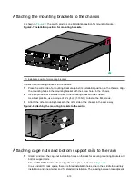
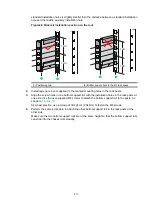
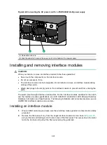
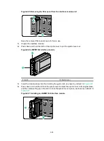
Orient the fan module with the adapter facing upwards. Grasp the handle of the fan module with
one hand and support the fan module bottom with the other. Slide the fan module along the
guide rails into the slot until the fan module is fully seated in the slot and has a firm contact with
the backplane. See
The fan module and the fan module slot each have an alignment hole. Orient the fan module as
indicated by alignment holes. Ensure that the alignment hole in the fan module is aligned with
that in the switch after the fan module installation.
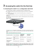
Figure2-17 Installing a FAN-80B-1-B fan module
1
2
Alignment hole of the fan tray
Содержание S9820-8C-SAN
Страница 37: ...3 30...


