3-4
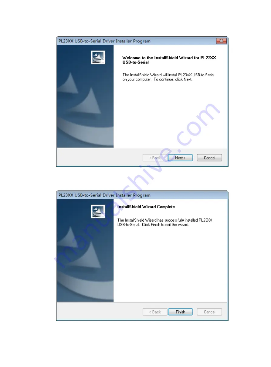
Figure3-4 Driver installation wizard
5.
Click
Finish
after the drive installation is completed.
Figure3-5 Finishing the driver installation
Страница 1: ...0 12A1 or PSR450 12 power supply 2 21 Installing a PSR180 12A F or PSR180 12A B power supply 2 22 Removing a PSR250 12A or PSR250 12A1 power supply 2 23 Removing a PSR450 12D power supply 2 24 Removin...
Страница 2: ...Configuring basic IRF settings 4 8 Connecting the physical IRF ports 4 8 Verifying the IRF fabric setup 4 8 5 Maintenance and troubleshooting 5 1 Power supply failure 5 1 Symptom 5 1 Solution 5 1 Fan...
Страница 3: ...n an unstable case or desk The switch might be severely damaged in case of a fall Ensure good ventilation of the equipment room and keep the air inlet and outlet vents of the switch free of obstructio...
Страница 4: ...anliness Dust buildup on the chassis might cause electrostatic adsorption and dust corrosion resulting in poor contact of metal connectors and contact points This might shorten the device s lifetime a...
Страница 5: ...pelines The air inlet of the equipment room must be away from such pollution sources Use environmentally friendly materials to decorate the equipment room Avoid using organic materials that contains h...
Страница 6: ...overvoltage or overcurrent caused by lightning strikes route interface cables only indoors Laser safety WARNING The switch is Class 1 laser device Disconnected optical fibers or transceiver modules mi...
Страница 7: ...ng the switch CAUTION Keep the tamper proof seal on a mounting screw on the chassis cover intact and if you want to open the chassis contact H3C for permission Otherwise H3C shall not be liable for an...
Страница 8: ...tion Turn on the circuit breakers Operating correctly Turn off the circuit breakers Troubleshoot the switch No Yes End Connect interface cables Ground the switch Install fan trays Install power suppli...
Страница 9: ...stance between the front and rear rack posts If the rack depth is in the range of 327 to 494 mm 12 87 to 19 45 in orient the rear mounting brackets with the wide flange inside the rack If the rack dep...
Страница 10: ...ail kit as shown in Figure2 7 S6520X 30QC EI S6520X 54QC EI S6520X 30QC HI S6520X 54QC HI S6520X 30HC EI S6520X 54HC EI S6520X 30HC HI S6520X 54HC HI Provided Provided Optional S6520X 30HF EI S6520X 5...
Страница 11: ...to the switch 2 Screw hole for attaching the bracket to the rack 3 M4 screw Figure2 6 Rear mounting bracket and shoulder screw 1 Screw hole for attaching the bracket to the rack 2 Shoulder screw Figu...
Страница 12: ...mounting bracket against the chassis side panel Align the mounting bracket installation holes with the screw holes in the chassis To install the mounting brackets at the port side mounting position s...
Страница 13: ...ly attached to the switch chassis See Attaching the front mounting brackets to the switch 3 Attach cage nuts to the front rack posts 4 One person supports the bottom of the switch and moves the switch...
Страница 14: ...stallation position near the power supply side The port side mounting is similar To attach the front mounting brackets and shoulder screws to the switch 1 Wear an ESD wrist strap Make sure the strap m...
Страница 15: ...posts Make sure the corresponding cage nuts on the left and right rear rack posts are at the same height 3 Orient the rear mounting brackets with the wide flange inside or outside the rack as require...
Страница 16: ...front rack posts Make sure the corresponding cage nuts on the left and right front rack posts are at the same height 4 One person supports the chassis bottom with one hand holds the front part of the...
Страница 17: ...ith the wide flange of the rear mounting brackets inside the rack S6520X 30QC EI switch as an example Figure2 16 Mounting the switch in the rack with the wide flange of the rear mounting brackets outs...
Страница 18: ...gure2 17 Attaching the front mounting brackets and extension brackets to the switch port side mounting position for the mounting brackets S6520X 54HF EI switch as an example NOTE Secure the front moun...
Страница 19: ...at the extension rails have been correctly attached to the rear rack posts See Attaching the extension rails to the rack 4 Attach cage nuts to the front rack posts and make sure they are at the same l...
Страница 20: ...heat dissipation Do not place heavy objects on the switch To mount the switch on a workbench 1 Verify that the workbench is sturdy and reliably grounded 2 Place the switch with bottom up and clean the...
Страница 21: ...ower and data lines from damages Prevents electrical fires lightning strokes electromagnetic coupling interferences ESD damages and ensures correct operation of the power system Select a grounding met...
Страница 22: ...ding sign 4 Grounding hole 5 Grounding cable Connecting the grounding cable to a grounding strip 1 Use needle nose pliers to bend the bare metal part to the shape as shown in Figure2 23 Make sure the...
Страница 23: ...and treat the joint for corrosion protection Figure2 24 Grounding the switch by burying the grounding conductor into the earth ground 1 Grounding screw 2 Chassis rear panel 3 Grounding cable 4 Earth 5...
Страница 24: ...lots Select fan trays for the switch that match the ventilation requirements at the installation site The LSWM1FANSCE fan tray provides power supply side intake and port and chassis side exhaust airfl...
Страница 25: ...ns the switch does not check the preferred airflow direction at system start You only need to ensure consistent airflow directions of all fan trays on the switch If the airflow directions of the fan t...
Страница 26: ...Removal procedure CAUTION To prevent damage to the power supply and the connectors on the backplane insert the power supply gently If you encounter a hard resistance when inserting the power supply p...
Страница 27: ...9 Removing the filler panel from the target power supply slot 3 Unpack the power supply Make sure the power supply model is as required Keep the packaging box and packaging bag for the power supply se...
Страница 28: ...el Figure2 31 Removing the filler panel 3 Unpack the power supply and verify that the power supply model is correct 4 Correctly orient the power supply with the power supply slot use the letters on th...
Страница 29: ...strap Make sure the strap makes good skin contact and is reliably grounded 2 Disconnect the power cord 3 Press the latch on the power supply towards the handle side and pull the power supply part way...
Страница 30: ...r supply As shown in Table3 2 use a flathead screwdriver to loosen the two screws on the power cord connector and then pull the connector out 3 Holding the power supply handle with one hand and using...
Страница 31: ...ower supply To remove a PSR180 12A B power supply 1 Wear an ESD wrist strap and make sure it makes good skin contact and is reliably grounded 2 Disconnect the power cord 3 Loosen the captive screws on...
Страница 32: ...pply To connect the power cord for a PSR250 12A1 power supply 1 Wear an ESD wrist strap Make sure the strap makes good skin contact and is reliably grounded 2 Plug the female connector of the power co...
Страница 33: ...rist strap and make sure it makes good skin contact and is reliably grounded 2 Attach the power cord retainer clip supplied with the power supply into the two holes next to the AC input power receptac...
Страница 34: ...input receptacle on the power supply as shown by callout 1 in Figure2 39 If you orient the DC power cord connector upside down you cannot insert it into the DC power input receptacle 2 Use a flathead...
Страница 35: ...30QC HI S6520X 54QC HI S6520X 30HC HI and S6520X 54HC HI switches each provide two expansion slots on the rear panel For the expansion cards available for the switch see Hardware Information and Spec...
Страница 36: ...Figure2 41 b Gently push the expansion card into the slot along the guide rails until the expansion card has good contact with the chassis See callout 2 in Figure2 41 c Close the ejector lever as sho...
Страница 37: ...ptive screw on the expansion card 3 Fully open the ejector lever Skip this step for an expansion card that does not have an ejector lever 4 Gently pull the expansion card out of the slot along the gui...
Страница 38: ...2 32 NOTE For information about lightning protection for the switch see H3C Lightning Protection Guide...
Страница 39: ...guration terminal As shown in Table3 1 three types of console cables can be used for connecting the switch to a configuration terminal As a best practice use a serial console cable for connection The...
Страница 40: ...witch end A DB9 to RJ45 console cable is an 8 core shielded cable with a crimped RJ 45 connector at one end for connecting to the serial console port of the switch and a DB 9 female connector at the o...
Страница 41: ...ng installs the driver on the Windows system To install the driver on other operating systems see the installation guide in the driver compression package named by the corresponding operating system T...
Страница 42: ...3 4 Figure3 4 Driver installation wizard 5 Click Finish after the drive installation is completed Figure3 5 Finishing the driver installation...
Страница 43: ...cable To connect to the PC through a micro USB console cable 1 Connect the standard USB Type A connector to the USB port of the PC 2 Connect the micro USB Type B connector to the micro USB console po...
Страница 44: ...3 6 Figure3 7 Device Driver Installation Wizard 6 Click Continue Anyway if the following dialog box appears Figure3 8 Software Installation 7 Click Finish...
Страница 45: ...about the terminal emulator programs see the user guides for these programs Configure the terminal parameters as follows Bits per second 9 600 Data bits 8 Parity None Stop bits 1 Flow control None St...
Страница 46: ...with software versions For more information about Boot ROM menu options see the software matching release notes for the device After the startup process is completed you can access the CLI to configu...
Страница 47: ...lowchart Figure4 1 IRF fabric setup flowchart To set up an IRF fabric Step Description 1 Plan IRF fabric setup Plan the installation site and IRF fabric setup parameters Planning IRF fabric size and t...
Страница 48: ...equals the total switching capacities of all member switches Plan the installation site depending on your network solution as follows Place all IRF member switches in one rack for centralized high den...
Страница 49: ...you must bind a minimum of one physical port to it When connecting two neighboring IRF member switches you must connect the physical ports of IRF port 1 on one switch to the physical ports of IRF por...
Страница 50: ...hernet ports 10G 5G 2 5G 1000BASE T autosensing Ethernet ports SFP ports QSFP ports Physical ports on interface modules and the front panel can be bound to the same IRF logical interface All physical...
Страница 51: ...hysical port only when it operates at 100 Gbps S6520X 54HF EI S6520X 54HF HI 48 SFP ports on the front panel 6 QSFP28 ports on the front panel All physical ports to be bound to an IRF logical interfac...
Страница 52: ...ed IRF connection schemes by using SFP cables and SFP transceiver modules and fibers All these schemes use a ring topology IMPORTANT In these schemes all physical IRF ports are located on the same sid...
Страница 53: ...4 7 Figure4 5 IRF fabric topology 1 2 3 4 5 6 7 8 9 1 2 3 4 5 6 7 8 9...
Страница 54: ...settings see H3C S6520X EI S6520X HI Switch Series Virtual Technologies Configuration Guide Connecting the physical IRF ports Use twisted pair SFP QSFP SFP28 QSFP28 cables or SFP QSFP SFP28 QSFP28 tra...
Страница 55: ...display irf configuration Display IRF fabric topology information display irf topology NOTE To avoid IP address collision and network problems configure a minimum of one multi active detection MAD me...
Страница 56: ...54QC EI S6520X 30HC EI S6520X 54HC EI S6520X 30QC HI S6520X 54QC HI S6520X 30HC HI and S6520X 54HC HI switches The status LED on a power supply in combination with the power supply status LED on the...
Страница 57: ...not have display when the switch is powered on Solution To resolve the issue 1 Verify that the power supply is supplying power to the switch correctly 2 Verify that the console cable is correctly conn...