background image


11 

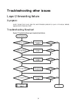
2. 

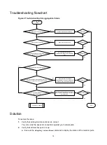
Verify that the member ID of each member device is unique: 

a. 

Execute the 

display irf


command to view the member ID of each member device. 

b. 

Assign a unique member ID to each member. 

  If you are adding a new member device to an existing IRF fabric, assign the member 

device a member ID that is not being used in the IRF fabric. 

  If you are merging IRF fabrics, make sure each member device in these IRF fabrics has 

a unique member ID. 

3. 

Verify that the IRF port bindings and physical IRF link connections are correct: 


IMPORTANT: 

When you connect two neighboring IRF members, you must connect the physical ports of 
IRF-port 1 on one member to the physical ports of IRF-port 2 on the other. 


a. 

Execute the 

display irf configuration

 command on each member device, and 

check the 

IRF-Port1

 and 

IRF-Port2

 fields for IRF port bindings. 

b. 

Verify that all or none of the physical ports in a port group are used for IRF connection.  

The following are physical port grouping rules: 

  The 10GBASE-T ports or SFP+ ports are grouped by port number in order, starting from 

1. Each port group contains four ports. 

  The 10-GE interfaces split from a QSFP+ port belong to the same port group. 

c. 

Verify that the physical IRF connections are consistent with the IRF port bindings. 

d. 

If there are binding errors or connection inconsistencies, reconfigure the IRF port bindings 
or reconnect the physical IRF ports. 

4. 

Verify that the IRF links are 10 Gbps or 40 Gbps: 

a. 

Verify that the transceiver modules or cables for IRF connection are labeled with 

10Gbps

SFP+

40Gbps

, or 

QSFP+

b. 

Replace a transceiver module or cable if it is not for 10-Gbps or 40-Gbps connection. 

5. 

(Optional.) Verify that transceiver modules at the two ends of an IRF link are the same type. 

If the transceiver modules are not the same type, replace them to be the same type. 

Skip this step if you are using SFP+ or QSFP+ cables to connect IRF member devices. 

6. 

Verify that all IRF links are up: 

a. 

Execute the 

display irf topology

 command, and then check the 

Link

 field. 

  If the 

Link

 field for each IRF port does not display 

DOWN

, go to step 

7

. 

  If the 

Link

 field for an IRF port displays 

DOWN

, go to step 

b

. 

b. 

Execute the 

display irf link


command, and then check the 

Status

 field of the physical 

ports bound to the IRF port. 

  If the field displays 

DOWN

 or 

ADM

 (administratively down) for all the physical ports, 

remove the link failures or use the 

undo shutdown

 command to bring up the 

administratively down ports. 

  If the field displays 

UP

 for at least one of the physical ports, go to step 

c

. 

c. 

Save the configuration, and then execute the 

irf-port-configuration active


command in system view to activate the IRF port configuration. 


IMPORTANT: 

Activating IRF port configuration requires a reboot. To prevent configuration loss, you must 
save the configuration before you execute the 

irf-port-configuration active


command.  


Содержание S6300 Series

Страница 1: ...reproduced or transmitted in any form or by any means without prior written consent of New H3C Technologies Co Ltd Except for the trademarks of New H3C Technologies Co Ltd any trademarks that may be m...

Страница 2: ...wchart 7 Solution 7 Related commands 8 Troubleshooting IRF 9 IRF fabric establishment failure 9 Symptom 9 Troubleshooting flowchart 10 Solution 10 Related commands 12 Troubleshooting Ethernet link agg...

Страница 3: ...rding failure 24 Symptom 24 Troubleshooting flowchart 25 Solution 25 Related commands 26 Protocol flapping 26 Symptom 26 Troubleshooting flowchart 26 Solution 26 Fan failure 27 Symptom 27 Troubleshoot...

Страница 4: ...mation for common hardware issues NOTE This section describes how to troubleshoot unexpected switch reboot power supply failure and fan tray failure To troubleshoot ports see Troubleshooting ports Une...

Страница 5: ...in to the switch through the console port and restart the switch If the system reports that a CRC error has occurred or that no system software image is available reload the system software image The...

Страница 6: ...he power source If it has been disconnected from the power source The switch is being powered up with another power supply connect the power source to it b Verify that the power supply surface is clea...

Страница 7: ...tom A trap or log is generated indicating that an operating fan tray or a newly installed fan tray is faulty Solution To resolve the issue 1 Execute the display fan command to display the operating st...

Страница 8: ...operating temperature below 60 C 140 F the switch can be used temporarily 4 If the issue persists contact H3C Support Related commands This section lists the commands that you might use for troublesho...

Страница 9: ...on To resolve the issue 1 Execute the display qos acl resource command and then check the Remaining field for ACL resources insufficiency If this field displays 0 the ACL hardware resources are exhaus...

Страница 10: ...splay qos policy control plane slot slot number b If the QoS policy does not contain a class behavior association associate the traffic behavior with the traffic class c If the QoS policy contains a c...

Страница 11: ...ACL is configured incorrectly reconfigure it If the ACL is configured correctly go to step 3 3 If the issue persists contact H3C Support Related commands This section lists the commands that you migh...

Страница 12: ...9 Troubleshooting IRF This section provides troubleshooting information for common issues with IRF IRF fabric establishment failure Symptom An IRF fabric cannot be established...

Страница 13: ...No Yes Yes No Yes No Yes You cannot add devices to the IRF fabric Yes No Member ID unique Modify IRF port bindings or reconnect physical ports Number of members fewer than the upper limit IRF port bin...

Страница 14: ...ure the IRF port bindings or reconnect the physical IRF ports 4 Verify that the IRF links are 10 Gbps or 40 Gbps a Verify that the transceiver modules or cables for IRF connection are labeled with 10G...

Страница 15: ...leshooting IRF Command Description display interface Displays interface information Use this command to verify that each IRF port has at least one physical port in up state display irf Displays IRF fa...

Страница 16: ...ation This section provides troubleshooting information for common issues with Ethernet link aggregation Link aggregation failure Symptom Some member ports fail to be placed in Selected state and link...

Страница 17: ...ational key attribute configurations same as the reference port Set operational key attribute configurations same as the reference port No Yes Set the number of member ports less than or equal to allo...

Страница 18: ...rence port 6 Verify that the number of member ports in the aggregation group does not exceed the configured maximum number of Selected ports a Execute the link aggregation selected port maximum comman...

Страница 19: ...To resolve the issue Speed duplex match at both ends Speed duplex match on port and transceiver module Configure matching speed duplex Resolved Configure matching speed duplex A fiber port failed to...

Страница 20: ...rt operating correctly 4 Verify that the transceiver module and cable are operating correctly a Use the display transceiver alarm interface command to display the alarms present on the transceiver mod...

Страница 21: ...and to set the rate and duplex mode for the port 2 Replace the network cable with a new one to verify that the network cable is in good condition 3 Replace the local port with a new one to verify that...

Страница 22: ...c information Displays or saves running status data for multiple feature modules display interface brief Displays brief interface information display transceiver alarm interface Displays alarms presen...

Страница 23: ...ayer 2 packet loss failure Incoming error packets No Yes Yes Troubleshoot the problem End No Yes Layer 2 packet loss Packets filtered by ACLs or QoS policies Troubleshoot the problem Port blocked No T...

Страница 24: ...ulticast max ratio 100 Unicast max ratio 100 PVID 13 MDI type Automdix Port link type Access Tagged VLANs None Untagged VLANs 13 Port priority 0 Last link flapping Never Last clearing of counters Neve...

Страница 25: ...hip port with which the interface is associated H3C probe debug port mapping slot 1 Interface Unit Port Name Combo Active IfIndex MID Link XGE1 0 1 0 1 xe0 no no 0x1 4 up XGE1 0 2 0 2 xe1 no no 0x2 4...

Страница 26: ...ing or display ipv6 source binding command If IP source guard is configured but the packets match no entry further troubleshoot the issue based on the way the binding entries are created 3 Verify that...

Страница 27: ...Displays whether an ACL has been successfully applied to an interface for packet filtering display qos policy Displays user defined QoS policy configuration information display qos policy interface Di...

Страница 28: ...es are the same by using the display mac address command If the output interfaces are not the same execute the reset command to clear the ARP entries Then the switch can learn ARP entries again 3 Veri...

Страница 29: ...routing table display mac address Display MAC address entries display fib Display FIB entries Protocol flapping Symptom The switch cannot send or receive protocol packets Troubleshooting flowchart Fig...

Страница 30: ...1 ISIS 0 0 0 200 D On SMAC 8 2 ESIS 0 0 0 100 S On SMAC 8 3 CLNP 0 0 0 100 S On SMAC 8 4 VRRP 0 0 0 1024 S On SMAC 8 5 UNKNOWN_IPV4MC 0 0 0 100 S On SMAC 8 6 UNKNOWN_IPV6MC 0 0 0 100 S On SMAC 8 7 IPV...

Страница 31: ...FanDirectionFault Airflow Direction Port to power Prefer Airflow Direction Power to port b If the preferred airflow direction is different use the fan prefer direction slot slot number power to port p...

Страница 32: ...erate correctly check whether the fans are damaged If the fan status is fault replace the fan tray 3 If the issue persists contact H3C Support Related commands This section lists the commands that you...

Отзывы: