background image


2-19 

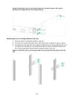
Figure2-15 Mounting the switch in the rack by using mounting brackets D (S5120V3-10P-LI) 


Rack-mounting the switch by using front and rear mounting 
brackets 

This installation method is applicable to the S5120V3-30MS-UPWR-DP-EI switch. 

Attaching the front mounting brackets and shoulder screws to the switch 

The switch provides two installation positions on its side for the front mounting brackets. One is near 
the power supply side and the other is near the port side. The following procedure describes how to 
attach  the front mounting brackets to the installation  position  near the port side. The  power 
supply-side mounting is similar. 

To attach the front mounting brackets and shoulder screws to the switch: 

1. 

Place the wide flange of the front mounting bracket against the chassis side panel. Align the 
mounting bracket installation holes with the screw holes in the chassis. See 

Figure2-16

. 

2. 

Use M4 screws to attach the mounting bracket to the chassis, and then fasten the M4 screws. 
As a best practice, use a torque of 12 kgf-cm (1.18 Nm) to fasten the M4 screws. 

3. 

Repeat the preceding two steps to attach the other mounting bracket to the chassis. 

4. 

Unpack the shoulder screws and attach them to the chassis. As a best practice, use a torque of 
12 kgf-cm (1.18 Nm) to fasten the shoulder screws. 

Two installation positions as red-marked in 

Figure2-16

 are available for shoulder screws. 

Select one as required. 

Содержание S5120V3-EI Series

Страница 1: ...pply 2 30 Connecting the power cord 2 31 Connecting the AC power cord for the fixed AC power supply 2 31 Connecting the power cord for a PSR360 56A PSR720 56A or PSR1110 56A power supply 2 32 Connecti...

Страница 2: ...ii Symptom 5 50 Solution 5 50 Fan tray failure 5 51 Configuration terminal issues 5 51 No display on the configuration terminal 5 51 Garbled display on the configuration terminal 5 51...

Страница 3: ...28S HPWR EI S5120V3 54S PWR EI LS 5120V3 54S PWR EI S5120V3 30MS UPWR DP EI LS 5120V3 30MS UPWR DP EI S5120V3 LI switch series Non PoE models S5120V3 10P LI LS 5120V3 10P LI LS 5120V3 10P LI GL S5120V...

Страница 4: ...cated on its rear panel or top panel Safety recommendations To avoid equipment damage or bodily injury read the following safety recommendations before installation Note that the recommendations do no...

Страница 5: ...with high humidity Do not touch the device with wet hands Temperature humidity For correct operation and long service life of your switch maintain the temperature and humidity in the equipment room a...

Страница 6: ...hen you install or remove the device or components Make sure the wrist strap has good skin contact and is reliably grounded Cleanliness For more information see Cleanliness Corrosive gas prevention Th...

Страница 7: ...the equipment room at their average values Make sure the corrosive gas concentrations do not exceed 30 minutes per day at their maximum values To control corrosive gases use the following guidelines A...

Страница 8: ...idity are uncontrolled Incompletely enclosed or shielded places Places near pollution sources Simple equipment rooms ordinary houses garages corridors and direct ventilation cabinets near pollution so...

Страница 9: ...vided with the switch on other devices Laser safety WARNING Disconnected optical fibers or transceiver modules might emit invisible laser light Do not stare into beams or view directly with optical in...

Страница 10: ...0V3 54P PWR SI 2150A0BP Rear mounting bracket kit including two rear mounting brackets and two shoulder screws 1 kit provided S5120V3 30MS UPWR DP EI SOHO SWITCH FL 02 Front mounting bracket kit inclu...

Страница 11: ...cord in this table is a standard power cord in China 1 provided for the switch with a fixed power supply 1 provided with removable power supplies All switch models N A DC power cord 1 provided with r...

Страница 12: ...wise H3C shall not be liable for any consequence Figure2 1 Hardware installation flow Start Install the switch Ground the switch Connect the power cords Verify the installation Turn on the circuit bre...

Страница 13: ...SI Q switch or the S5120V3 LI switch series the front mounting brackets can be installed only near the port side See Rack mountin g the switch by using front mounting brackets S5120V3 EI switch series...

Страница 14: ...of 429 to 595 mm 16 89 to 23 43 in orient the rear mounting brackets with the wide flange inside the rack If the rack depth is in the range of 274 to 440 mm 10 79 to 17 32 in and the distance from th...

Страница 15: ...lder screw 1 Shoulder screw 2 Screw hole for attaching the mounting bracket to the rack Installation procedure at a glance Figure2 4 Procedure for installing the switch in a 19 inch rack by using fron...

Страница 16: ...bracket installation holes with the screw holes in the chassis 2 Fasten the M4 screws to secure the mounting bracket to the switch As a best practice use a torque of 12 kgf cm 1 18 Nm to fasten the M...

Страница 17: ...2 15 Figure2 7 Attaching mounting bracket B to the port side mounting position S5120V3 28S HPWR EI Figure2 8 Attaching mounting bracket B to the power supply side mounting position S5120V3 28S HPWR EI...

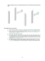
Страница 18: ...the rack 1 Wear an ESD wrist strap and make sure it makes good skin contact and is reliably grounded 2 Verify that the front mounting brackets have been securely attached to the switch chassis See Att...

Страница 19: ...are level and secure As a best practice use a torque of 30 kgf cm 2 94 Nm to fasten the M6 screws Figure2 11 Mounting the switch in the rack port side mounting position for mounting brackets A on an...

Страница 20: ...13 Mounting the switch in the rack power supply side mounting position for mounting brackets B on an S5120V3 28S HPWR EI Figure2 14 Mounting the switch in the rack by using mounting brackets C S5120V...

Страница 21: ...wer supply side mounting is similar To attach the front mounting brackets and shoulder screws to the switch 1 Place the wide flange of the front mounting bracket against the chassis side panel Align t...

Страница 22: ...Orient the rear mounting brackets with the wide flange inside or outside the rack as required 3 Use M6 screws and cages nuts user supplied to attach the rear mounting brackets to the rear rack posts A...

Страница 23: ...3 Attach cage nuts to the front rack posts 4 One person supports the chassis bottom moves the switch to an appropriate position based on the installation positions of the front mounting brackets and...

Страница 24: ...19 Mounting the switch in the rack with the wide flange of the rear mounting brackets inside the rack Figure2 20 Mounting the switch in the rack with the wide flange of the rear mounting brackets outs...

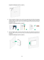
Страница 25: ...ctrical lines exist in the wall Leave a minimum clearance of 10 mm 0 39 in around the chassis for heat dissipation The S5120V3 SI and S5120V3 LI switch series support wall mounting These switches are...

Страница 26: ...r to fasten the screw into the screw anchor Leave 1 5 mm 0 06 in between the screw head and the wall for hanging the switch Figure2 23 Installing the switch on a wall 2 3 Align the installation holes...

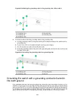
Страница 27: ...itch with a grounding strip Grounding the switch with a grounding conductor buried in the earth ground NOTE The chassis views and power supply and grounding terminal positions in the following figures...

Страница 28: ...ex nut to secure the cable to the post Figure2 26 Connecting the grounding cable to a grounding strip 1 Grounding post 2 Grounding strip 3 Grounding cable 4 Hex nut Grounding the switch with a groundi...

Страница 29: ...ance between the switch grounding terminal and grounding point and make sure the resistance is less than 0 1 b Use a grounding resistance tester to measure the grounding resistance of the grounding st...

Страница 30: ...are the same for the PSR360 56A PSR560 56D PSR720 56A and PSR1110 56A power supplies The following uses the PSR360 56A power supply as an example Installing a power supply CAUTION Follow the forward...

Страница 31: ...r supply secure for future use 4 Correctly orient the power supply with the lettering on it facing upward Align the power supply with the power supply slot Grasping the power supply handle with one ha...

Страница 32: ...e handle and then pull the power supply part way out along the guide rails 4 Grasping the power supply handle with one hand supporting the bottom with the other pull the power supply slowly out of the...

Страница 33: ...a PSR360 56A PSR720 56A or PSR1110 56A power supply PSR560 56D 48 VDC power source in the equipment room Connecting the DC power cord for a PSR560 56D power supply RPS1600 A Connecting the AC power c...

Страница 34: ...ly 1 Wear an ESD wrist strap and make sure it makes good skin contact and is reliably grounded 2 Plug the female connector end of the power cord into the power receptacle on the power supply see callo...

Страница 35: ...7 The power cord connector and power receptacle are designed to prevent misalignment If you cannot insert the connector into the receptacle re orient the connector rather than use excessive force to p...

Страница 36: ...If a power line is routed from outdoors verify that a surge protected power strip is used for the switch NOTE For information about lightning protection for the switch see H3C Lightning Protection Gu...

Страница 37: ...ple from the serial console port Figure3 1 Connecting the switch to a configuration terminal As shown in Figure3 1 three types of console cables can be used for connecting the switch to a configuratio...

Страница 38: ...switch first connect the PC end To disconnect a PC from an operating switch first disconnect the switch end A DB9 to RJ45 serial console cable is an 8 core shielded cable with a crimped RJ 45 connecto...

Страница 39: ...nstalls the driver on the Windows system To install the driver on other operating systems see the installation guide in the driver compression package named by using the corresponding operating system...

Страница 40: ...the switch to a configuration terminal for example a PC by using a micro USB console cable 1 Connect the standard USB connector to the USB port of the PC 2 Connect the micro USB connector to the micro...

Страница 41: ...3 39 Figure3 5 Device Driver Installation Wizard 6 Click Continue Anyway Figure3 6 Software Installation 7 Click Finish...

Страница 42: ...erminal emulator programs see the user guides for these programs Configure the terminal parameters as follows Bits per second 9600 Data bits 8 Stop bits 1 Parity None Flow control None Powering on the...

Страница 43: ...ce and menu options differ with software versions For more information about Boot ROM menu options see the software matching release notes for the device After the startup completes you can access the...

Страница 44: ...e same group to set up an IRF fabric Table4 1 Switch groups Group Model Group 1 S5120V3 EI switch series Group 2 S5120V3 28P HPWR LI Q S5120V3 20P LI S5120V3 28P LI S5120V3 52P LI S5120V3 28P PWR LI S...

Страница 45: ...cheme 2 Install IRF member switches See Installing the switch in a 19 inch rack Mounting the switch on a workbench or Mounting the switch on a wall 3 Connect grounding cables and power cords See Groun...

Страница 46: ...in the IRF fabric at the CLI of the master switch IRF member switches automatically elect a master You can affect the election result by assigning a high member priority to the intended master switch...

Страница 47: ...2 shows the physical ports that can be used for IRF connection and the port use restrictions Table4 2 Candidate physical IRF ports and their use restrictions Chassis Candidate physical IRF ports Use r...

Страница 48: ...T autosensing Ethernet ports on the front panel All physical ports to be bound to an IRF logical interface must have the same data rate An SFP port can be used as an IRF physical port only when it op...

Страница 49: ...nsceiver models and cables see ports in S5120V3 EI S5120V3 LI S5120V3 SI Switch Series Hardware Information and Specifications If the IRF member switches are far away from one another use SFP SFP tran...

Страница 50: ...ber priorities and IRF port bindings Follow these guidelines when you configure the switches Assign the master switch higher member priority than any other switch Bind physical ports to IRF port 1 on...

Страница 51: ...network management station See the fundamentals configuration guide for the switch series 4 Verify that you can manage all member switches as if they were one node 5 Display the running status of the...

Страница 52: ...uses removable power supplies You can observe the power supply status LEDs PWR1 and PWR2 on the front panel of the switch in combination with the status LEDs on the power supplies to identify power s...

Страница 53: ...resolve the issue 1 Verify that the power system is operating correctly 2 Verify that the switch is operating correctly 3 Verify that the console cable has been connected correctly 4 Verify that the...

Страница 54: ...5 52 2 If the issue persists contact H3C Support...

Отзывы: