background image


52 

RT-MSR810-LM-CNDE-SJK 

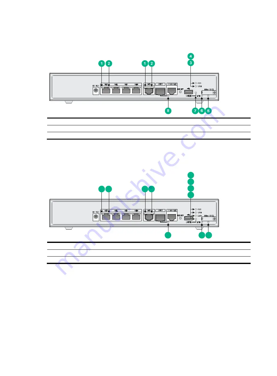
Figure 57 Front panel LEDs 


(1) GE port yellow LED 

(2) GE port green LED 

(3) VPN status LED 

(4) System status LED (SYS) 

(5) Micro SD card LED 

(6) LTE LED 

(7) CNDE LED 

(8) SFP port LED 


RT-MSR810-W-LM 

Figure 58 Front panel LEDs 


(1) GE port yellow LED 

(2) GE port green LED 

(3) CNDE LED 

(4) 2.4G WLAN LED 

(5) VPN status LED 

(6) System status LED (SYS) 

(7) Micro SD card LED 

(8) LTE LED 

(9) SFP port LED 


1

2

1

2

7

8

9

3

4

5

6

Содержание MSR810

Страница 1: ...H3C MSR810 Routers Installation Guide New H3C Technologies Co Ltd http www h3c com Document version 6W108 20190528...

Страница 2: ...respective owners Notice The information in this document is subject to change without notice All contents in this document including statements information and recommendations are believed to be acc...

Страница 3: ...t you replace with actual values Square brackets enclose syntax choices keywords or arguments that are optional x y Braces enclose a set of required syntax choices separated by vertical bars from whic...

Страница 4: ...s Convention Description Represents a generic network device such as a router switch or firewall Represents a routing capable device such as a router or Layer 3 switch Represents a generic switch such...

Страница 5: ...ardware model configuration or software version It is normal that the port numbers sample output screenshots and other information in the examples differ from what you have on your device Documentatio...

Страница 6: ...unding the router 14 Attaching the grounding cable to the ring terminal 14 Grounding the router with a grounding strip 14 Grounding the router with a grounding conductor buried in the earth ground 15...

Страница 7: ...T MSR810 W LM HK 39 RT MSR810 LM GL 40 RT MSR810 W LM GL 41 RT MSR810 LME 42 RT MSR810 LMS EA RT MSR810 LMS RT MSR810 LUS 42 Technical specifications 43 Appendix B LEDs 50 LEDs 50 RT MSR810 50 RT MSR8...

Страница 8: ...o avoid any equipment damage or bodily injury read the following safety recommendations before installation Note that the recommendations do not cover every possible hazardous condition Safety symbols...

Страница 9: ...ays wear an ESD wrist strap Make sure the wrist strap makes good skin contact and is reliably grounded No ESD wrist strap is provided with the router Prepare it yourself To attach an ESD wrist strap 1...

Страница 10: ...the chassis might result in electrostatic adsorption which causes poor contact of metal components and contact points especially when indoor relative humidity is low In the worst case electrostatic ad...

Страница 11: ...system coupling To prevent EMI perform the following tasks If AC power is used use a single phase three wire power receptacle with protection earth PE to filter interference from the power grid Keep...

Страница 12: ...mpatibility Model 4G antenna WLAN antenna RT MSR810 LM RT MSR810 LM CNDE SJK RT MSR810 W LM RT MSR810 LM HK RT MSR810 W LM HK RT MSR810 LM GL RT MSR810 W LM GL 2 N A RT MSR810 W RT MSR810 W LM RT MSR8...

Страница 13: ...as required Figure 3 Installation tools and equipment Pre installation checklist Item Requirements Result Installation site Ventilation There is a minimum clearance of 100 mm 3 94 in around the air in...

Страница 14: ...ng stations radar stations and high frequency devices Electromagnetic shielding for example shielded interface cables is used as required Lightning protection The router is reliably grounded The power...

Страница 15: ...ver intact and if you want to open the chassis contact H3C for permission Otherwise H3C shall not be liable for any consequence Installation prerequisites You have read Preparing for installation care...

Страница 16: ...down on the workbench and attach the rubber feet to the four round holes in the chassis bottom 2 Place the router upside up on the workbench Start Determine the installation position End Connect the...

Страница 17: ...e locations on the wall Make sure the two holes are 160 mm 6 30 in horizontally apart 2 Drill holes with a minimum depth of 22 mm 0 87 in in the marked locations 3 Hammer an anchor into each hole unti...

Страница 18: ...10 PoE and are optional for the other models The RT MSR810 LME RT MSR810 LMS RT MSR810 LMS EA and RT MSR810 LUS routers do not support rack mounting To install the router in a rack 1 Use a mounting br...

Страница 19: ...nuts as shown in Figure 8 a Insert one ear of a cage nut into the marked installation hole b Use a flathead screwdriver to push another ear into the same hole Figure 8 Installing cage nuts 3 Attach m...

Страница 20: ...Figure 9 Attaching mounting brackets to the router 4 Use M6 screws to attach the mounting brackets on the router to the front rack posts as shown in Figure 10 Figure 10 Securing the router to the rac...

Страница 21: ...l 1 Cut the grounding cable to the desired length 2 Use the wire stripping pliers to peel 5 mm 0 20 in of insulation sheath from one end of the grounding cable 3 Add a heat shrink tubing on the cable...

Страница 22: ...uter with a grounding conductor buried in the earth ground If the installation site does not have any grounding strips but earth ground is available hammer a 0 5 m 1 64 ft or longer angle iron or stee...

Страница 23: ...lot is active at a time As a best practice use the master slot if you are to install only one SIM card You can use the sim switch to command to specify the active slot For more information about the c...

Страница 24: ...the cover Figure 15 Installing a Micro SD card Installing an SD card CAUTION To avoid damaging the SD card slot do not use excessive force when you install an SD card The router cannot read data from...

Страница 25: ...10 LMS RT MSR810 LMS EA RT MSR810 LUS No 4G antenna is provided with the RT MSR810 LME RT MSR810 LMS and RT MSR810 LUS routers Purchase one yourself if required To install a 4G antenna 1 Change the an...

Страница 26: ...nas for the RT MSR810 W RT MSR810 W LM RT MSR810 W LM HK and RT MSR810 W LM GL routers and four WLAN antennas for the RT MSR810 W DB router To install a WLAN antenna 1 Change the angle of the antenna...

Страница 27: ...MSR810 LM CNDE SJK RT MSR810 W LM RT MSR810 LM HK RT MSR810 W LM HK RT MSR810 LM GL RT MSR810 W LM GL To install a GPS antenna 1 Attach the male connector of the GPS antenna to the GPS antenna port on...

Страница 28: ...supply power to a terminal the terminal must support PoE To supply power to a terminal through PoE 1 Connect one end of the cable to an Ethernet port on the router 2 Connect the other end of the cable...

Страница 29: ...cables 1 Connect one end of the cable to an Ethernet port on the router 2 Connect the other end of the cable to the Ethernet port on a host 3 Examine the port LEDs on the router For more information a...

Страница 30: ...C is more commonly used 2 Connect the DB 9 connector female of the console cable to the RS 232 serial port on the configuration terminal and the RJ 45 connector to the console port of the router Figur...

Страница 31: ...MSR810 W DB RT MSR810 W RT MSR810 W LM RT MSR810 LM HK RT MSR810 W LM HK RT MSR810 LM GL RT MSR810 W LM GL RT MSR810 LME RT MSR810 LMS RT MSR810 LMS EA RT MSR810 LUS The RT MSR810 10 PoE router uses...

Страница 32: ...LM CNDE SJK RT MSR810 W DB RT MSR810 W RT MSR810 W LM RT MSR810 LM HK RT MSR810 W LM HK RT MSR810 LM GL RT MSR810 W LM GL Figure 24 Assembling the RT MSR810 LMS EA adapter Figure 25 Connecting the po...

Страница 33: ...ctly to the configuration terminal and other devices Parameters are configured correctly on the configuration terminal Accessing the router for the first time WARNING Before powering on the router loc...

Страница 34: ...main image files Loading file flash msr810 cmw710 system e030401 bin Done Loading file flash msr810 cmw710 security e030401 bin Done Loading file flash msr810 cmw710 voice e030401 bin Done Loading fil...

Страница 35: ...is ready to configure when you see the following prompt Sysname 5 Configure basic settings for the router For information about configuring basic setting for the router see Fundamentals Configuration...

Страница 36: ...the power source correctly 2 Verify that the power source is operating correctly 3 Verify that the power cord is in good condition 4 If the issue persists contact H3C Support No display on the configu...

Страница 37: ...settings are correct 2 If the issue persists contact H3C Support 3G 4G SIM card and 4G antenna failures Symptom After a 3G 4G SIM card and 4G antennas are installed on the router and the router is pow...

Страница 38: ...the network connectivity is lost When you check the configuration the configuration is very complicated and it is hard to locate the errors In this case you must configure the router again Solution If...

Страница 39: ...re for illustration only RT MSR810 Figure 27 Front view 1 Power adapter receptacle 2 Gigabit Ethernet LAN ports GE1 to GE4 3 Gigabit Ethernet WAN port GE0 4 Gigabit fiber port SFP5 5 Console port 6 US...

Страница 40: ...hernet LAN ports GE1 to GE4 3 Gigabit Ethernet WAN port GE0 4 Gigabit fiber port SFP5 5 Console port 6 USB port 0 7 Micro SD card slot 8 USB port 1 9 Reset button RESET Figure 30 Rear view 1 Grounding...

Страница 41: ...GE1 to GE4 3 Gigabit Ethernet WAN ports GE0 4 Gigabit fiber port SFP5 5 Console port 6 USB port 0 7 Micro SD card slot 8 USB port 1 9 Reset button RESET Figure 32 Rear view 1 Grounding screw 2 2 4G WL...

Страница 42: ...LAN ports GE1 to GE4 3 Gigabit Ethernet WAN port GE0 4 Gigabit fiber port SFP5 5 Console port 6 USB port 7 Micro SD card slot 8 Reset button RESET Figure 34 Rear view 1 Grounding screw 2 LTE antenna...

Страница 43: ...ernet LAN ports GE1 to GE4 3 Gigabit Ethernet WAN port GE0 4 Gigabit fiber port SFP5 5 Console port 6 USB port 7 Micro SD card slot 8 Reset button RESET Figure 36 Rear view 1 Grounding screw 2 LTE ant...

Страница 44: ...Gigabit Ethernet WAN port GE0 4 Gigabit fiber port SFP5 5 Console port 6 USB port 7 Micro SD card slot 8 Reset button RESET Figure 38 Rear view 1 Grounding screw 2 LTE antenna port 1 3 2 4G WLAN anten...

Страница 45: ...t button RESET 6 USB port 7 SD card slot Figure 40 Rear view 1 AC power receptacle 2 Grounding screw 3 Security slot RT MSR810 LM HK Figure 41 Front view 1 Power adapter receptacle 2 Gigabit Ethernet...

Страница 46: ...adapter receptacle 2 Gigabit Ethernet LAN ports GE1 to GE4 3 Gigabit Ethernet WAN port GE0 4 Gigabit fiber port SFP5 5 Console port 6 USB port 7 Micro SD card slot 8 Reset button RESET Figure 44 Rear...

Страница 47: ...et LAN ports GE1 to GE4 3 Gigabit Ethernet WAN port GE0 4 Gigabit fiber port SFP5 5 Console port 6 USB port 7 Micro SD card slot 8 Reset button RESET Figure 46 Rear view 1 Grounding screw 2 LTE antenn...

Страница 48: ...3 Gigabit Ethernet WAN port GE0 4 Gigabit fiber port SFP5 5 Console port 6 USB port 7 Micro SD card slot 8 Reset button RESET Figure 48 Rear view 1 Grounding screw 2 LTE antenna port 1 3 2 4G WLAN ant...

Страница 49: ...FE0 to FE3 Figure 50 Rear view 1 Console port 2 4G SIM card slots SIM0 and SIM1 3 Grounding screw RT MSR810 LMS EA RT MSR810 LMS RT MSR810 LUS Figure 51 Front view 1 LTE antenna port 0 2 GPS antenna p...

Страница 50: ...port GE LAN port 4 4 4 8 FE port N A N A N A N A Micro SD card slot 1 1 1 N A SD card slot N A N A N A 1 Built in 3G 4G module N A N A N A N A LTE antenna port N A N A N A N A WLAN antenna port N A 2...

Страница 51: ...810 W LM HK Console port 1 1 1 1 1 USB port 1 1 1 1 1 GE WAN port 1 1 1 1 1 GE SFP port 1 1 1 1 1 GE LAN port 4 4 4 4 4 FE port N A N A N A N A N A Micro SD card slot 1 1 1 1 1 Built in 3G 4G module T...

Страница 52: ...24 W 24 W 24 W 24 W 24 W PoE power N A N A N A N A N A Operating temperature 0 C to 40 C 32 F to 104 F Operating humidity 5 RH to 90 RH non condensing Table 8 Technical specifications 3 Item RT MSR810...

Страница 53: ...put voltage 100 VAC to 240 VAC 50 to 60Hz 100 VAC to 240 VAC 50 to 60Hz 100 VAC to 240 VAC 50 to 60Hz 100 VAC to 240 VAC 50 to 60Hz Power rating 10 W 10 W 10 W 10 W PoE power N A N A N A N A Operating...

Страница 54: ...C 50 to 60Hz 100 VAC to 240 VAC 50 to 60Hz Power rating 24 W 24 W PoE power N A N A Operating temperature 0 C to 40 C 32 F to 104 F Operating humidity 0 RH to 95 RH non condensing Table 10 Stick 4G an...

Страница 55: ...G LTE magnetic mount antenna specifications Item Specification Frequency range 680 to 960 MHz 1710 to 2700 MHz Voltage standing wave ratio VSWR 2 0 1 5 Input impedance 50 ohms Gain 2 dBi peak Polariza...

Страница 56: ...49 Item Specification Weight 25 g 0 88 oz Operating temperature 40 C to 85 C 40 F to 185 F...

Страница 57: ...r more than 4 seconds to reboot the router and restore the factory settings RT MSR810 Figure 53 Front panel LEDs 1 GE port yellow LED 2 GE port green LED 3 System status LED SYS 4 Micro SD card LED 5...

Страница 58: ...3 5G WLAN LED 4 2 4G WLAN LED 5 VPN status LED 6 System status LED SYS 7 Micro SD card LED 8 SFP port LED RT MSR810 LM Figure 56 Front panel LEDs 1 GE port yellow LED 2 GE port green LED 3 VPN status...

Страница 59: ...s LED 4 System status LED SYS 5 Micro SD card LED 6 LTE LED 7 CNDE LED 8 SFP port LED RT MSR810 W LM Figure 58 Front panel LEDs 1 GE port yellow LED 2 GE port green LED 3 CNDE LED 4 2 4G WLAN LED 5 VP...

Страница 60: ...1 SD card LED 2 PoE LED 3 VPN status LED 4 System status LED SYS RT MSR810 LM HK Figure 60 Front panel LEDs 1 GE port yellow LED 2 GE port green LED 3 VPN status LED 4 System status LED SYS 5 Micro S...

Страница 61: ...CNDE LED 4 2 4G WLAN LED 5 VPN status LED 6 System status LED SYS 7 Micro SD card LED 8 LTE LED 9 SFP port LED RT MSR810 LM GL Figure 62 Front panel LEDs 1 GE port yellow LED 2 GE port green LED 3 VPN...

Страница 62: ...LED 3 CNDE LED 4 2 4G WLAN LED 5 VPN status LED 6 System status LED SYS 7 Micro SD card LED 8 LTE LED 9 SFP port LED RT MSR810 LME Figure 64 Front panel LEDs 1 System status LED SYS 2 VPN status LED...

Страница 63: ...elf test Flashing yellow 8 Hz The extended segment does not exist Steady yellow The system software image does not exist Off No power input or exceptions have occurred VPN status LED VPN Steady on A m...

Страница 64: ...Ds on Very strong 4G signal RSSI 75 dBm Three green LEDs on Strong 4G signal 85 dBm RSSI 75 dBm Two green LEDs on Weak 4G signal 95 dBm RSSI 85 dBm One green LED on Very weak 4G signal 110 dBm RSSI 95...

Страница 65: ...lashing yellow Data is being received or transmitted at 10 100 Mbps Off No link is present PoE LED Steady green PoE is operating correctly Flashing green 8 Hz PoE has failed Off PoE is disabled SD car...

Отзывы: