H3C MSR 20 Series Скачать руководство пользователя страница 23


16 

Installation process 
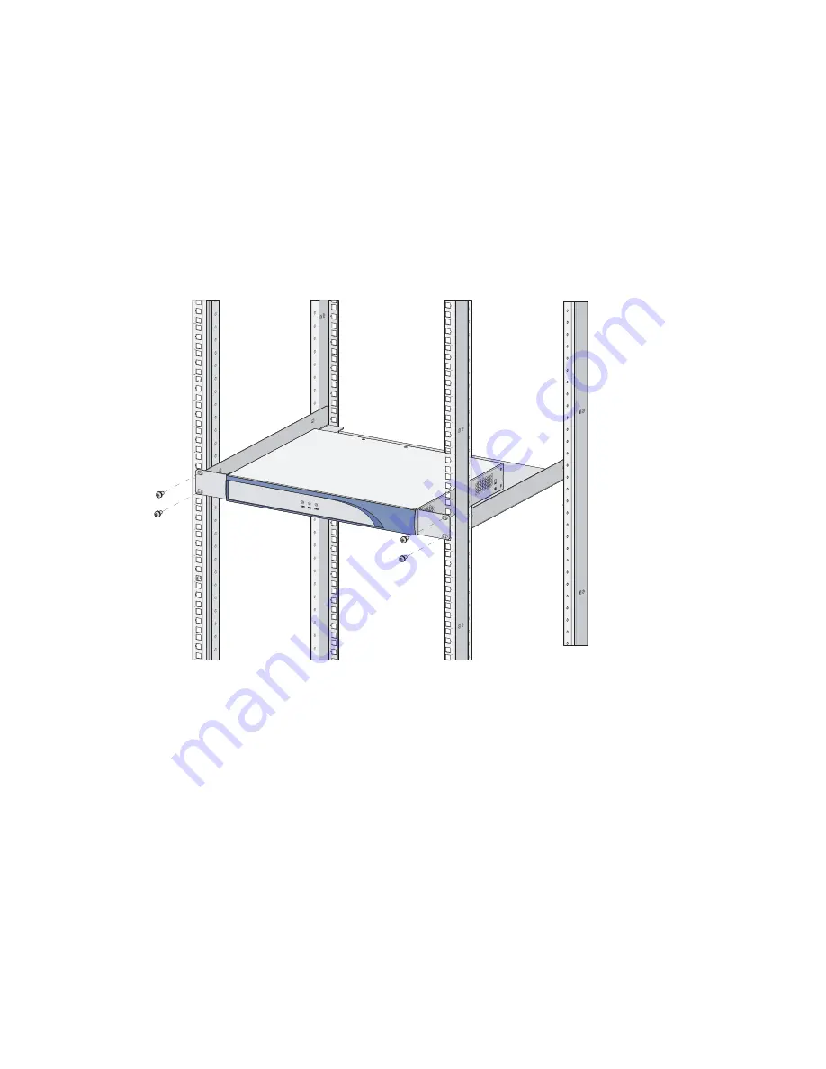
Step1


Check the grounding and stability of the rack. Use the screws to fix the mounting brackets at both sides 

of the front panel or the rear panel of the router. 

Step2


Put the router in a rack tray. For MSR 20-40 routers, use dedicated ears mounted on the rear panel if no 

tray is available. Depending on the actual situation, slide the router along the chassis guides to an 

appropriate place. 

Step3


Fasten the mounting brackets with the recess screws to fix the router in the rack horizontally and firmly. 

The specifications of recess screws should satisfy the installation requirements and the surface of the 

screws should be anti-rust.  

Figure 9


Installing MSR 20 Router in a rack 


Содержание MSR 20 Series

Страница 1: ...H3C MSR 20 Routers Installation Guide Hangzhou H3C Technologies Co Ltd http www h3c com Document version T2 08047K 20101217 C 1 05...

Страница 2: ...gzhou H3C Technologies Co Ltd All other trademarks that may be mentioned in this manual are the property of their respective owners Notice The information in this document is subject to change without...

Страница 3: ...ion describes the conventions used in this documentation set Symbols Convention Description WARNING An alert that calls attention to important information that if not understood or followed can result...

Страница 4: ...rs Interface Module Manual Provides a complete guide to hardware installation and hardware specifications MSR Series Routers Configuration guides Describe software features and configuration procedure...

Страница 5: ...olutions Provides information about products and technologies as well as solutions Technical Support Documents Software Download Provides the documentation released with the software version Technical...

Страница 6: ...nd Meters and Equipments 12 Installation 14 Installation Process 14 Installing the Cabinet 14 Installing the Router 14 Installing the Router on a Workbench 15 Installing the Router in a Cabinet 15 Ins...

Страница 7: ...ootWare Through Serial Interface 49 XModem Protocol Overview 49 Modifying Serial Interface Parameters 50 Upgrading BootWare 51 Upgrading an Application Program through a Serial Interface 53 Maintainin...

Страница 8: ...includes the following models MSR 20 20 MSR 20 21 MSR 20 40 Router Model and Structure The MSR 20 Routers include MSR 20 20 MSR 20 21 and MSR 20 40 These three models are similar in chassis structure...

Страница 9: ...54 W 100 W Operating temperature 0 C to 40 C 32 F to 104 F 0 C to 40 C 32 F to 104 F 0 C to 40 C 32 F to 104 F Relative humidity non condensing 5 to 90 5 to 90 5 to 90 NOTE The Boot ROM stores the Bo...

Страница 10: ...9 Auxiliary port AUX 10 USB interface 11 CF card Panel LEDs The following table gives the features of MSR 20 20 router LEDs Table 2 Front panel LEDs of an MSR 20 20 router LED Description PWR Power L...

Страница 11: ...no data is being transmitted or received Blinking means data is being transmitted or received CF Steady green means a CF card is present Green and blinking means the CF card is reading writing data To...

Страница 12: ...r LED ON means power is on OFF means power is off SYS System operating LED Green and fast blinking means the system is booting Green and slow blinking means the system is operating normally Yellow and...

Страница 13: ...vent data corruption do not remove the running CF card Steady yellow means the present CF card is malfunctioning Steady OFF means no CF card is present or the present CF card cannot be identified by t...

Страница 14: ...CF CF card LED Steady green means the CF card is in place and can be identified by the router Blinking green means the CF card is being accessed and cannot be removed Steady yellow means the CF card i...

Страница 15: ...SIC DSIC interface cards providing various interfaces such as synchronous asynchronous serial interface Ethernet interface E1 T1 ISDN BRI PRI ADSL audio interface and Layer 2 switching interface and...

Страница 16: ...o implement the encryption decryption EC and CNG of voices VCPM Voice Co Processing Module processes the voice data in combination with VPM Voice co processing module RT VCPM 8 channel voice processin...

Страница 17: ...f the insulating materials and shorten the service life of the router The requirements on the temperature and humidity for MSR 20 are shown in the following table Table 9 Temperature humidity requirem...

Страница 18: ...ard please touch the edge of the circuit board and avoid contacting the devices on it Requirements on Electromagnetic Environments The interference sources no matter where they come from affect the ro...

Страница 19: ...this operation is incorrect and may seriously damage the router or endanger the operator Please follow the correct operation procedures for sake of safety CAUTION indicates that during the installatio...

Страница 20: ...Optional cables Meters and equipment Hub or LAN switch Console terminal it could be a PC Equipment related to the selected modules Multimeter CAUTION None of the above mentioned installation tools met...

Страница 21: ...the Cabinet For cabinet installation methods refer to the part discussing cabinet installation Skip this section if you want to mount your router on the tabletop or the rack of another vendor Install...

Страница 22: ...installed on a clean workbench The operations are very simple but still you should be aware of the following items Ensure the stability and well grounding of the workbench Reserve a space of 10 cm 3 9...

Страница 23: ...dicated ears mounted on the rear panel if no tray is available Depending on the actual situation slide the router along the chassis guides to an appropriate place Step3 Fasten the mounting brackets wi...

Страница 24: ...y connect the PGND cable when installing or using the router The power input end of MSR 20 router is connected to a noise filter The neutral point of the noise filter is directly connected to the chas...

Страница 25: ...avoid lightning which may damage the router itself and even the peer device Connecting the Power Cord The MSR 20 20 20 21 20 40 router is available with AC powered units Power Input and PGND Table 13...

Страница 26: ...power source at your installation site Step3 Place the power switch of the router to the ON position Step4 Check that the PWR LED on the front panel of the router is on for correct connection Connecti...

Страница 27: ...p information of the router if the connection is correct Fixed Interfaces Ethernet Interface Ethernet interface MSR 20 Routers are available with fixed 100Base TX FE interface s and Ethernet modules c...

Страница 28: ...ork cables shielded cables are preferred for electromagnetic compatibility sake Connecting the Ethernet cable Follow the steps below to connect an Ethernet cable Step1 Connect one end of the Ethernet...

Страница 29: ...to router You can make crossover cables yourself as needed NOTE In making network cables shielded cables are preferred for electromagnetic compatibility sake Connecting the Ethernet cable Follow the s...

Страница 30: ...refer to MSR Series Routers Configuration Guide Interface Modules The MSR 20 Routers are available with various types of interface modules For detailed information refer to MSR Series Routers Interfa...

Страница 31: ...eps to install a DSIC interface card Step1 Remove the blank panel covering the slot and keep it for future use Step2 Determine the interface card type Step3 Loosen the captive screws with a Philips sc...

Страница 32: ...slide rail Step3 Install a blank panel if no cards are to be installed in the slot Verifying Installation During router installation you must verify installation each time you power on the router mak...

Страница 33: ...port on the router and DB 9 connector to the serial interface of a PC as shown in the following figure Figure 21 Local configuration through Console port Devece PC Console cable Setting the parameter...

Страница 34: ...o parity check stop bit to 1 and flow control to none Then click OK to return to the HyperTerminal window Figure 23 Setting serial interface parameters Step3 Set HyperTerminal properties Select File P...

Страница 35: ...minal for configuration is open and whether the settings are done Whether the CF card is loosed WARNING Before powering on the router the user should be aware where the switch of the power supply to t...

Страница 36: ...008 CPU Type MPC8248 CPU L1 Cache 16KB CPU Clock Speed 400MHz Memory Type SDRAM Memory Size 384MB Memory Speed 100MHz BootWare Size 4096KB Flash Size 4MB cfa0 Size 64MB CPLD Version 130 0 PCB Version...

Страница 37: ...bers of all the interfaces on the router according to the division of the subnets Step5 Configure the routes If it is necessary to enable a dynamic routing protocol the user should configure the relat...

Страница 38: ...a view The user can use these commands to switch between different configuration views In general only certain commands can be executed under a particular view But some common commands such as ping an...

Страница 39: ...interfaces are on Slot 0 Different interfaces on an interface module share the same slot number X For every interface Y starts from 0 and Y indicates the interface sequence on the interface module fr...

Страница 40: ...through the menu of the basic section Application files The router is available with Dual Image function By default the system defines and attempts to boot in order with three boot files main backup...

Страница 41: ...uter is successfully loaded To change the sequence of these configuration files or modify them refer to Maintaining Application and Configuration Files on page 53 The details about the three configura...

Страница 42: ...version If the current version is inconsistent with the version used on the FIP the system upgrades the BootWare automatically Check the current version of BootWare and application program before upg...

Страница 43: ...t interface connected to it Ethernet 0 0 in this example is set to 192 168 0 2 Use the ping command to check whether the connection successful Backing up and restoring application programs and configu...

Страница 44: ...g To leave the existing filename unchanged press the enter key Use the dir command to view the application files and the available space of the CF card ensure that the CF card has enough space to stor...

Страница 45: ...e router Similarly you can also upgrade the main application file by downloading a new application file to overwrite the original main application file The above operations are performed in user view...

Страница 46: ...executes an action accordingly and returns the execution result to the client Use the following command to enable the FTP service SYSTEM ftp server enable Start FTP server Add an authorized username...

Страница 47: ...Kbytes sec Use the following command to recover the backup file to the router ftp put main bin main bin 200 Port command okay 150 Opening BINARY mode data connection for main bin 226 Transfer complete...

Страница 48: ...and back up files ftp get main bin main bin cfa0 main bin has been existing Overwrite it Y N y 200 PORT command successful 150 File status OK about to open data connection 226 Closing data connection...

Страница 49: ...the system displays Press Ctrl B to enter extended boot menu the system prompts for the BootWare password Please input BootWare password After you enter the correct password the system enters the mai...

Страница 50: ...eration Menu BootWare operation submenu For details about the submenu refer to BootWare operation submenu on page 45 8 Clear Super Password Remove the super password You need to use the super password...

Страница 51: ...Application File 3 Update Backup Application File 4 Update Secure Application File 5 Modify Ethernet Parameter 0 Exit To Main Menu Ensure The Parameter Be Modified Before Downloading Enter your choic...

Страница 52: ...ubmenu Enter 7 in the main BootWare menu to enter the BootWare operation submenu BootWare Operation Menu Note the operating device is cfa0 1 Backup Full BootWare 2 Restore Full BootWare 3 Update BootW...

Страница 53: ...y IP Address 0 0 0 0 FTP User Name user FTP User Password password Table 23 Ethernet parameters settings description Parameter Description Clear field To clear the current field input a and then press...

Страница 54: ...t so complex and low cost file transfer services TFTP provides unreliable data transfer services over UDP and does not provide any access authorization and authentication mechanism It employs timeout...

Страница 55: ...fault boot file of the system Enter 4 when the above information appears File CONTROL Note the operating device is cfa0 1 Display All File s 2 Set Application File type 3 Set Configuration File type 4...

Страница 56: ...er 4 in the BootWare submenu and the system displays BOOTWARE OPERATION ETHERNET SUB MENU 1 Update Full BootWare 2 Update Extend BootWare 3 Update Basic BootWare 4 Modify Ethernet Parameter 0 Exit To...

Страница 57: ...u to enter the serial interface submenu Then enter 5 and the system prompts for changing a baud rate BAUDRATE SET Note indicates the current baudrate Change The HyperTerminal s Baudrate Accordingly Ba...

Страница 58: ...n the HyperTerminal to 9600 bps after upgrading the BootWare This ensures that the information can be displayed on the console terminal after system boot or reboot Upgrading BootWare First enter 7 in...

Страница 59: ...sfer Send file in the HyperTerminal window The following window appears Figure 36 Send file dialog box Click Browse to select the application program file to be downloaded and select XModem for the Pr...

Страница 60: ...efer to Modifying Serial Interface Parameters on page 50 for details Then enter 2 in the serial interface submenu The system displays Please Start To Transfer File Press Ctrl C To Exit Waiting CC Sele...

Страница 61: ...22165484 Dec 20 2007 09 42 28 M cfa0 main bin 0 Exit Enter file No Enter the number of the file to be modified and press Enter the system will prompt you to modify the file type Modify the file attri...

Страница 62: ...d then the system displays The file you selected is cfa0 backup bak Delete it Y N Y Deleting Done CAUTION You can set the main or backup attribute only for the application and configuration file in th...

Страница 63: ...in the current configuration If you use the set authentication password cipher 123456 command to set a password the password is stored in cipher text Step4 Save the new configuration SYSTEM save NOTE...

Страница 64: ...page 45 for details Enter 1 under the menu and the system starts to backup the entire BootWare The system prompts Will you backup the Basic BootWare Y N Y Begin to backup the Basic BootWare Done Will...

Страница 65: ...n the back panel keep the ground cable connected Step3 Put the router on level ground and have the back panel face you Loosen the captive screws fastening the back panel with Phillips screwdriver Step...

Страница 66: ...59 Figure 39 Turn the screwdriver in the hole on MSR 20 20 20 21 Figure 40 Remove install captive screws of MSR 20 40 Figure 41 Turn the screwdriver on MSR 20 20 20 21...

Страница 67: ...users operation without permission Do not replace the hardware unless necessary and under the guidance of technical staff Ensure that no electricity is present before servicing the device to avoid bo...

Страница 68: ...6 7 8 9 1 2 1 Power module 2 CF card slot 3 SDRAM slot 4 ESM slot0 5 ESM slot1 6 SIC slot 7 Fan 8 VCPM slot 9 VPM slot Installing Removing CF Card Structure Figure 44 Front view of CF card Installing...

Страница 69: ...ard following these steps Step1 Check the CF card LED to make sure it is not blinking and then proceed Step2 Press the spring button to release the internal spring clip making the card out of the slot...

Страница 70: ...erally you need to do that in the following situations More memory is required for the updated application program maintaining a large routing table or processing tasks that consume large memory The e...

Страница 71: ...he slot Step4 Press the memory bar vertically until you hear a click This indicates the memory bar is fixed within the slot Step5 Check if the spring clip has locked the memory bar slot Figure 50 Inst...

Страница 72: ...sis Cover for details to find the card Step3 Install the card bracket on specified position on the main board and fasten it on the board Step4 Align the card interface with the slot and press down ver...

Страница 73: ...66 Figure 53 Fasten the card on the bracket with screws NOTE Perform the steps inversely to remove the card...

Страница 74: ...the configuration system the console screen displays nothing or only illegible characters Symptom 1 After the router is powered on the console screen displays nothing Solution Step 1 Check that The p...

Страница 75: ...because the source file does not exist the network cable is not connected or the IP address of the PC is incorrect Make sure that the source file is in the TFTP FTP root directory the cable is connec...

Страница 76: ...E The bar code labels on the chassis and the FICs contain information about production and servicing Before you ask your agent for servicing provide its bar code If you do not set the parameters such...

Страница 77: ...ules 23 Internal Structure 60 Introduction 1 Introduction 33 M Maintaining Application and Configuration Files 53 Maintaining Application Program and Configuration Through Command Lines35 O Opening Cl...

Отзывы: