background image


1-7 

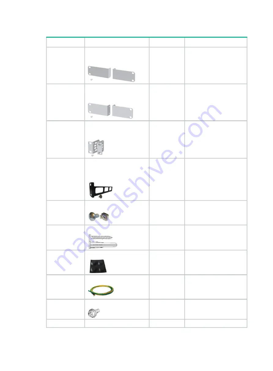
Table1-8 Installation accessories 

Code 

Description 

Quantity 

Applicable device models 

N/A 

Front mounting kit, including a 
pair of front mounting brackets 
and four M4 screws 


1 pair, provided 

FS5100-8S-PWR-EI 

FS5100-12S-EI 

FS5100-12MS-EI 

FS5100-12S-PWR-EI 

FS5100-12MS-PWR-EI 

N/A 

Front mounting kit, including a 
pair of front mounting brackets 
and four M4 screws 


1 pair, provided 

FS5100-20MS-EI 

FS5100-20MS-PWR-EI 

N/A 

Front mounting kit, including a 
pair of front mounting brackets 
and eight M4 screws 


1 pair, provided 

FS5100-52F-EI-PS 

N/A 

Rear mounting bracket kit, 
including a pair of rear mounting 
brackets and two shoulder 
screws 


1 pair, provided 

FS5100-52F-EI-PS 

N/A 

M6 screw and cage nut 


M6 screws: two, 
provided 

Cage nut: User 
supplied 

All models 

N/A 

Screw anchor and screw 


1 pair, provided 

All models except for 
FS5100-52F-EI-PS 

63200063 

Rubber feet


Four, provided 

All models 

0404A0DT 

Grounding cable 


1, provided 

All models 

N/A 

Grounding screw 


1, provided 

All models 

N/A 

AC power cord 

1, provided 

All models 

Содержание FS5100-EI Series

Страница 1: ...er grounding the switch 2 23 Installing and removing power supplies 2 24 Installing a power supply 2 24 Removing a power supply 2 25 Connecting the power cord 2 26 Connecting the AC power cord for the fixed AC power supply 2 26 Connecting the power cord for a PSR920 54A B power supply 2 27 Connecting DC power connectors and power cords 2 28 Verifying the installation 2 30 3 Accessing the switch fo...

Страница 2: ...wer supply failure 5 43 Symptom 5 43 Solution 5 43 Fan tray failure 5 43 Symptom 5 43 Solution 5 43 Configuration terminal issues 5 43 No display on the configuration terminal 5 43 Garbled display on the configuration terminal 5 44 ...

Страница 3: ...the recommendations do not cover every possible hazardous condition Before cleaning the switch remove all power cords from the switch Do not clean the switch with wet cloth or liquid Do not place the switch near water or in a damp environment Prevent water or moisture from entering the switch chassis Do not place the switch on an unstable case or desk Ensure good ventilation at the installation si...

Страница 4: ...e switch is intended for installation in a restricted access area A restricted access area can be accessed by skilled instructed or qualified personnel Temperature humidity For correct operation and long service life of your switch maintain the temperature and humidity in the equipment room at acceptable ranges Lasting high relative humidity can cause poor insulation electricity leakage mechanical...

Страница 5: ...ly To avoid ESD damage to the device or components always wear an ESD wrist strap when you install or remove the device or components Make sure the wrist strap has good skin contact and is reliably grounded Cleanliness For more information see Cleanliness Corrosive gas prevention The installation site must be free from corrosive gases such as acid gases and alkaline gases For more information see ...

Страница 6: ...actice control the corrosive gas concentrations in the equipment room at their average values Make sure the corrosive gas concentrations do not exceed 30 minutes per day at their maximum values To control corrosive gases use the following guidelines As a best practice do not build the equipment room in a place with a high concentration of corrosive gases Make sure the equipment room is not connect...

Страница 7: ...midity are uncontrolled Incompletely enclosed or shielded places Places near pollution sources Simple equipment rooms ordinary houses garages corridors and direct ventilation cabinets near pollution sources houses without direct exposure to sunlight or rain railway station platforms stadiums uncleaned rooms after decoration and rooms under decoration B1 outdoor general environment Unshielded place...

Страница 8: ...nded reliably Do not use the power cord provided with the switch on other devices Laser safety WARNING Disconnected optical fibers or transceiver modules might emit invisible laser light Do not stare into beams or view directly with optical instruments when the switch is operating The switch is a Class 1 laser device Installation tools No installation tools are provided with the switch Prepare the...

Страница 9: ...0MS PWR EI N A Front mounting kit including a pair of front mounting brackets and eight M4 screws 1 pair provided FS5100 52F EI PS N A Rear mounting bracket kit including a pair of rear mounting brackets and two shoulder screws 1 pair provided FS5100 52F EI PS N A M6 screw and cage nut M6 screws two provided Cage nut User supplied All models N A Screw anchor and screw 1 pair provided All models ex...

Страница 10: ... AC power cords vary depending on countries and regions The AC power cord in this table is a standard AC power cord in China 04042967 DB9 to RJ45 console cable 1 optional All models 0404A1EE USB to RJ45 console cable 1 optional All models N A DC power connector 4 provided FS5100 52F EI PS ...

Страница 11: ...y consequence Figure2 1 Hardware installation flow Start Mount the switch in a 19 in rack on a workbench on a wall or under a table Ground the switch Connect power cables Verify the installation Turn on the circuit breaker Operating correctly Turn off the circuit breaker Troubleshoot the switch Yes No End Optional Connect DC power connectors and power cables Install power supplies Removable power ...

Страница 12: ...ront and rear mounting brackets Installation procedure at a glance Figure2 2 Procedure for installing the switch in a 19 inch rack by using front mounting brackets Figure2 3 Procedure for installing the switch in a 19 inch rack by using front and rear mounting brackets NOTE If a rack shelf is available you can put the switch on the rack shelf slide the switch to an appropriate location and attach ...

Страница 13: ...ee C in Figure2 4 Rear mounting brackets See Figure2 5 Figure2 4 Mounting brackets 1 Screw hole for attaching the bracket to the switch 2 Screw hole for attaching the bracket to the rack post Figure2 5 Rear mounting bracket and shoulder screw 1 Shoulder screw 2 Screw hole for attaching the bracket to the rack post Attaching the mounting brackets to the switch 1 Align the mounting bracket installat...

Страница 14: ...s good skin contact and is reliably grounded 2 Verify that the mounting brackets have been securely attached to the switch chassis 3 Install cage nuts in the mounting holes in the rack posts No cage nuts are provided with the switch Prepare them yourself 4 One person holds the switch chassis and aligns the mounting brackets with the mounting holes in the rack posts and the other person attaches th...

Страница 15: ...nd shoulder screws to the switch 1 Wear an ESD wrist strap Make sure the strap makes good skin contact and is reliably grounded 2 Place the wide flange of the mounting bracket against the chassis side panel Align the mounting bracket installation holes with the screw holes in the chassis See Figure2 8 3 Use M4 screws supplied with the switch to attach the mounting bracket to the chassis As a best ...

Страница 16: ...r the power supply side Wide flange inside the rack 372 to 536 mm 14 65 to 21 10 in 372 to 507 mm 14 65 to 19 96 in Wide flange outside the rack 214 to 378 mm 8 43 to 14 88 in IMPORTANT For the rack doors to close easily after switch installation make sure the distance from the rear rack posts to the inner surface of the cabinet door is greater than 153 mm 6 02 in 214 to 349 mm 8 43 to 13 74 in IM...

Страница 17: ...k with the wide flange inside the rack Figure2 10 Attaching the rear mounting brackets to the rack with the wide flange outside the rack Mounting the switch in the rack 1 Wear an ESD wrist strap Make sure the strap makes good skin contact and is reliably grounded ...

Страница 18: ...the other and pushes the chassis into the rack gently Make sure the shoulder screws rest firmly on the upper edge of the rear mounting brackets See Figure2 11 and Figure2 12 5 The other person attaches the front mounting brackets by using M6 screws and cage nuts to the front rack posts Make sure the switch is installed securely in the rack See Figure2 11 and Figure2 12 As a best practice use a tor...

Страница 19: ...that the workbench is sturdy and reliably grounded 2 Place the switch with bottom up and clean the round holes in the chassis bottom with dry cloth 3 Attach the rubber feet to the four round holes in the chassis bottom 4 Place the switch with upside up on the workbench Mounting the switch on a wall CAUTION Before drilling holes in a wall make sure no electrical lines exist in the wall Leave a mini...

Страница 20: ...Figure2 13 Screw anchor and screw To mount the switch on a wall 1 Mark two installation holes on the wall Make sure the two holes are on the same horizontal line See Table2 5 for the distance requirement between the two holes Figure2 14 Installing the switch on a wall 1 2 Drill two holes with a diameter of 6 mm 0 24 in and a depth of 25 mm 0 98 in at the marked locations Hammer the screw anchors i...

Страница 21: ...2 19 Figure2 15 Installing the switch on a wall 2 Figure2 16 Installing the switch on a wall 3 Figure2 17 Installing the switch on a wall 4 ...

Страница 22: ...ket with the two screw holes in the chassis and then use M4 screws to secure the mounting bracket to the chassis Attach the other mounting bracket to the chassis in the same way 3 Use a marker to mark the installation holes under the table Make sure the two installation holes are at the same height 4 Use cross recessed pan head tapping screws to secure the switch to the table Use Table2 6 to selec...

Страница 23: ...ower and data line damages Electrical fires lightning strokes electromagnetic coupling interferences and ESD damages You can ground the switch in one of the following ways depending on the grounding conditions available at the installation site Grounding the switch by using a grounding strip Grounding the switch with a grounding conductor buried in the earth ground NOTE The chassis views and power...

Страница 24: ...0 Attaching the grounding cable to the grounding hole of the switch 1 Grounding screw 2 Ring terminal 3 Grounding sign 4 Grounding hole 5 Grounding cable 2 Connect the other end of the grounding cable to the grounding strip a Cut the grounding cable to a length according to the distance between the switch and the grounding strip b Peel 20 mm 0 79 in of insulation sheath by using a wire stripper c ...

Страница 25: ...ection Figure2 22 Grounding the switch by burying the grounding conductor into the earth ground 1 Grounding screw 2 Grounding cable 3 Earth 4 Joint 5 Grounding conductor 6 Chassis rear panel Verifying the connection after grounding the switch If you ground the switch with a grounding strip a Use a multimeter to measure the resistance between the switch grounding terminal and grounding point and ma...

Страница 26: ... damage and bodily injury follow the procedures in Figure2 23 and Figure2 24 to install and replace a power supply Figure2 23 Installation procedure Figure2 24 Removal procedure The installation and removal procedures are the same for power supplies This guide uses the PSR920 54A B power supply as an example Installing a power supply 1 Wear an ESD wrist strap and make sure it makes good skin conta...

Страница 27: ... inserting the power supply pull out the power supply realign it with the slot and then insert it again Figure2 26 Installing a power supply Removing a power supply 1 Wear an ESD wrist strap and make sure it makes good skin contact and is reliably grounded 2 Power off the power supply and remove the power cord 3 Press the latch towards the handle and pull the power supply along the guide rails unt...

Страница 28: ...S5100 12MS PWR EI FS5100 20MS EI FS5100 20MS PWR EI AC power source Connecting the AC power cord for the fixed AC power supply FS5100 52F EI PS Removable power supply Connecting the power cord for a PSR920 54A B power supply Connecting the AC power cord for the fixed AC power supply 1 Connect the plug of the AC power cord to the AC input power receptacle on the switch See Figure2 27 2 Use a cable ...

Страница 29: ...ly 1 Plug the female connector of the power cord into the power receptacle on the power supply as shown in Figure2 29 2 Use a cable tie to secure the power cord to the handle of the power supply as shown in Figure2 30 3 Connect the other end of the power cord to an AC power source Figure2 29 Connecting the power cord for a PSR920 54A B power supply ...

Страница 30: ... EI PS provides four power interfaces PI at the rear panel To supply power to the other devices you must connect DC power connectors to the PIs and connect DC power cords to the connectors To connect DC power connectors and power cords 1 Verify that the DC power connectors are not damaged Figure2 31 shows a DC power connector Figure2 31 DC power connector 1 Button 2 Shell 3 Pull latch 4 Release sl...

Страница 31: ...ires into the apertures in the connector and gently push the wires until they are firmly seated in the connector The tabs in the connector will automatically lock the wires in place If you cannot pull the wires out the wires are attached to the connector securely Figure2 33 Inserting wires into the connector 4 Insert the four DC power connectors into the PIs at the rear panel of the switch Figure2...

Страница 32: ...e the connector Figure2 35 Re wiring a DC power connector Verifying the installation After you complete the installation verify that There is enough space for heat dissipation around the switch and the rack or workbench is stable The grounding cable is securely connected The correct power source is used The power cords are correctly connected All the interface cables are cabled indoors If any cabl...

Страница 33: ...ided with a serial console cable Table3 1 Connection methods and console cables Connection method Console cable type Configuration terminal side connector Switch side connector Using the serial console port for connection DB9 to RJ45 console cable DB 9 female connector RJ 45 connector USB to RJ45 console cable USB connector RJ 45 connector The signal pinout for the RJ 45 connector of a serial cons...

Страница 34: ...with a crimped RJ 45 connector at one end for connecting to the serial console port of the switch and a DB 9 female connector at the other end for connecting to the serial port on a configuration terminal Figure3 2 DB9 to RJ45 console cable Table3 2 DB9 to RJ45 console cable signal pinout RJ 45 Signal DB 9 Signal 1 RTS 8 CTS 2 DTR 6 DSR 3 TXD 2 RXD 4 SG 5 SG 5 SG 5 SG 6 RXD 3 TXD 7 DSR 4 DTR 8 CTS...

Страница 35: ...installs the driver on the Windows system To install the driver on other operating systems see the installation guide in the driver compression package named by using the corresponding operating system To connect the switch to a configuration terminal by using a USB to RJ45 console cable 1 Click the following link or copy it to the address bar on your browser and download the USB to RJ45 console d...

Страница 36: ... a network device a Telnet site or an SSH site For more information about the terminal emulator programs see the user guides for these programs Configure the terminal parameters as follows Bits per second 9 600 Data bits 8 Stop bits 1 Parity None Flow control None Powering on the switch Before powering on the switch verify that the following conditions are met The power cord is correctly connected...

Страница 37: ...nu options differ with software versions For more information about Boot ROM menu options see the software matching release notes for the device After the startup completes you can access the CLI to configure the switch For more information about the configuration commands and CLI see the configuration guides and command references for the switch series ...

Страница 38: ... setup Plan the installation site and IRF fabric setup parameters Planning IRF fabric size and the installation site Identifying the master switch and planning IRF member IDs Planning IRF topology and connections Identifying IRF physical ports on the member switches Planning the cabling scheme Start Plan IRF fabric setup Install IRF member switches Connect the grounding cables and power cords Powe...

Страница 39: ...etermine which switch you want to use as the master for managing all member switches in the IRF fabric An IRF fabric has only one master switch You configure and manage all member switches in the IRF fabric at the CLI of the master switch IRF member switches automatically elect a master You can affect the election result by assigning a high member priority to the intended master switch For more in...

Страница 40: ...et up IRF connections only when operating at their highest speeds For example a 10 GE port must operate at 10 Gbps A 1 GE port must operate at 1 Gbps You can bind multiple ports to an IRF port for increased bandwidth and availability NOTE The following figures use the SFP ports on the FS5100 12S EI switch as an example For the ports that can be used for IRF connections see Table4 1 Figure4 2 IRF f...

Страница 41: ...llowing ports on the front panel SFP ports 10 100 1000BASE T autosensing ports All physical ports to be bound to an IRF port must have the same data rate The port must operate at its highest speed SFP port 10 Gbps 10 100 1000BASE T autosensing port SFP port 1 Gbps FS5100 12MS EI FS5100 12MS PWR EI FS5100 20MS EI FS5100 20MS PWR EI All the following ports on the front panel 5G 2 5G 1000 100BAS E T ...

Страница 42: ...eiver module and optical fiber or SFP cable For the available transceiver models and cables see ports in FS5100 EI Switch Series Hardware Information and Specifications If the IRF member switches are far away from one another use SFP SFP transceiver modules and optical fibers If the IRF member switches are all in one equipment room use twisted pair cables or SFP SFP cables As a best practice use r...

Страница 43: ...witches Assign the master switch higher member priority than any other switch Bind physical ports to IRF port 1 on one switch and to IRF port 2 on the other switch You perform IRF port binding before or after connecting IRF physical ports depending on the software release Execute the display irf configuration command to verify the basic IRF settings For more information about configuring basic IRF...

Страница 44: ...ber device display irf configuration Display IRF fabric topology information display irf topology NOTE To avoid IP address collision and network problems configure a minimum of one multi active detection MAD mechanism to detect the presence of multiple identical IRF fabrics and handle collisions For more information about MAD detection see the IRF configuration guide or virtual technologies config...

Страница 45: ...al APW100 Symptom A power supply LED on the front panel of the switch is not steady green Solution To resolve the issue 1 Verify that the power cord is correctly connected to the switch 2 Verify that the power supply model is as required 3 Verify that the power supply is installed correctly in the switch 4 Verify that the switch is operating in the acceptable temperature range 5 If the power suppl...

Страница 46: ...ta bits 8 Parity None Stop bits 1 Flow control None 5 Verify that the console cable is not faulty 6 If the issue persists contact H3C Support Garbled display on the configuration terminal Symptom The configuration terminal displays garbled text Solution To resolve the issue 1 Verify that the following settings are configured for the terminal Baud rate 9600 Data bits 8 Parity None Stop bits 1 Flow ...

Отзывы: