


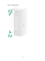


7-4
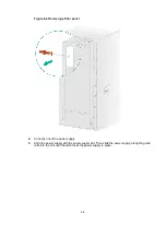
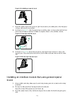
The number of screws for securing the protection box in
the actual number of screws on your interface module might differ from that.
Figure 7-4 Removing the protection box
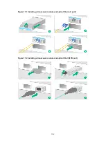
4.
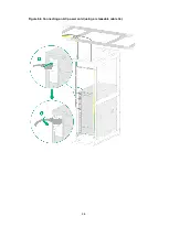
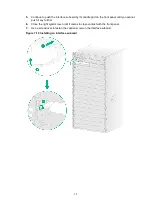
Correctly orient the interface module. Align the module with the slot and push it steadily into
the slot along the guide rails until about half of the module is in the slot.
Figure 7-5 Installing an interface module that uses detachable ejector levers
5.
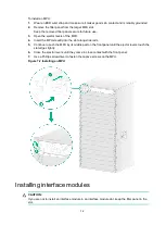
Attach the ejector lever holders to the chassis or cabinet and then remove the ejector levers
from the holders.
6.
Identify the "L" and "R" marks on the ejector levers and attach them to left and right ejector
lever retainers of the interface module, with the lettering on the ejector levers facing upward.
Содержание CR19000-16
Страница 16: ...4 3 Figure 4 3 Mounting the router in a rack...
Страница 25: ...6 8 Figure 6 6 Connecting an AC power cord using a releasable cable tie...
Страница 36: ...9 3 Figure 9 3 Installing a filler panel in a fabric module slot...
Страница 38: ...10 2 Figure 10 1 Installing a fan tray...
Страница 43: ...11 5 Figure 11 6 Routing signal cables...


