background image


GDM-350B User Manual 

10 

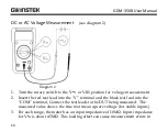
DC or AC Voltage Measurement 

(see diagram 2) 


Diagram 2


1.


Turn the rotary switch to the V   or V  position for voltage measurement.   

2.


Insert the red test lead into the “V” terminal and the black test lead into the 
“COM” terminal, Connect the test leads to the DUT being measured.  The 
measured value shows the true root mean square voltage (for stable inputs).  

3.


For each range, the meter has an input impedance of 10MΩ. Input impedance 
for V  is about 4.5MΩ. This loading effect can cause measurement errors in 

Содержание GDM-350B

Страница 1: ...Handheld Digital Multimeter GDM 350B USER MANUAL GW INSTEK PART NO 82DM 350B0M01 ISO 9001 CERTIFIED MANUFACTURER...

Страница 2: ...another language without prior written consent The information in this manual was correct at the time of printing However we continue to improve our products and therefore reserve the right to change...

Страница 3: ...n 7 The Meter Structure 8 MEASUREMENT OPERATION 9 DC or AC Voltage Measurement 10 DC Current Measurement 12 Resistance Measurement 14 Diode Measurement 16 Continuity Measurement 18 Transistor hFE meas...

Страница 4: ...sistance temperature the forward voltage drop of diodes transistors hFE and continuity tests The multi purpose socket is used to measure SMTs as well This operating manual covers information on safety...

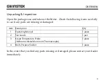
Страница 5: ...y to see if any parts are missing or damaged Item Description Qty 1 Operating Manual 1 piece 2 Test Leads 1 pair 3 K type Temperature Probe Nichrome Nickel Aluminum Thermocouple 1 piece 4 Multi Purpos...

Страница 6: ...ons 2 Inspect the test leads for damaged insulation or exposed metal Before using the meter replace any damaged test leads with test leads of the same model number or of the same electrical specificat...

Страница 7: ...ver 60V in DC or 30Vrms in AC special care should be taken 9 Do not use or store the meter in an environment with high temperature and humidity The performance of the meter may deteriorate if dampened...

Страница 8: ...anual 6 International Electrical Symbols Battery has insufficient charge Ground Warning Refer to the Operating Manual AC Alternating Current DC Direct Current Double Insulated Conforms to Standard of...

Страница 9: ...32 F 104 F Relative Humidity 0 C 30 C below 75 30 C 40 C below 50 Storing temperature 10 C 50 C 14 F 122 F 5 Electromagnetism Under 1V m emission Best Total Accuracy Specific Accuracy Measurement 5 Ov...

Страница 10: ...GDM 350B User Manual 8 The Meter Structure see diagram 1 1 LCD Display 2 Power Button 3 Rotary Switch 4 Input Terminals 5 HOLD Button diagram 1...

Страница 11: ...t check to see that the 9V battery is charged Turn the rotary switch to a measurement position If the battery charge is low the indicator will be displayed on LCD panel Ensure the input voltage or cur...

Страница 12: ...t the red test lead into the V terminal and the black test lead into the COM terminal Connect the test leads to the DUT being measured The measured value shows the true root mean square voltage for st...

Страница 13: ...f the circuit impedance is less than or equal to 10k the error is negligible 0 1 or less Warning To avoid damage to the meter please do not attempt to input more than 250V To avoid electrical shock pl...

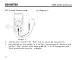
Страница 14: ...gram 3 1 Turn the rotary switch to the A position for current measurement 2 Insert the red test lead into the mA or 10A terminal and the black test lead into the COM terminal Connect the test leads to...

Страница 15: ...ent function If the correct range is not known select the highest range and work your way down to a lower range if needed Fuses are located on the mA and 10A current input terminals Never attempt conn...

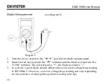
Страница 16: ...4 Diagram 4 1 Turn the rotary switch to the position for resistance measurement 2 Insert the red test lead into the terminal and the black test lead into the COM terminal Connect the test leads to the...

Страница 17: ...rements the resistance of the test leads must be deducted from the measured resistance Short the test leads and note the measurement result Deduct this value from the resistance of the DUT Measured Re...

Страница 18: ...the red test lead into the terminal and the black test lead into the COM terminal The red test lead is the black test lead is 3 In a circuit a good diode should still produce a forward voltage drop r...

Страница 19: ...polarity of the diode is incorrect To ensure the accuracy of the diode measurement disconnect power from the circuit and discharge all high voltage capacitors during the measurement The open circuit...

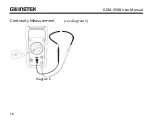
Страница 20: ...GDM 350B User Manual 18 Continuity Measurement see diagram 6 Diagram 6...

Страница 21: ...sound but if the resistance between both terminals is 10 it indicates a good connection and the buzzer will sound The resistance measurement is displayed on the LCD Unit Warning To maintain measuremen...

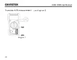
Страница 22: ...GDM 350B User Manual 20 Transistor hFE measurement see diagram 7 Diagram 7...

Страница 23: ...either PNP or NPN or SMT then connect the transistor to be measured to the corresponding jacks 4 The LCD display shows the hFE reference value The testing requirement basic current 10 A Vce of 2 3V W...

Страница 24: ...GDM 350B User Manual 22 Temperature Measurement see diagram 8 Diagram 8...

Страница 25: ...30 C you need to buy another type of thermocouple 4 When the LCD displays 1 it indicates that the K type thermocouple is not connected When the C terminal and the COM terminal are shorted the meter wi...

Страница 26: ...igits guaranteed for 1 year Operating temperature 23 C 5 C Relative Humidity 75 DC Voltage Range Resolution Accuracy 200mV 0 1mV 0 5 Reading 2 Digits 2000mV 1mV 20V 0 01V 200V 0 1V 250V 1V 0 8 Reading...

Страница 27: ...olution Accuracy 200V 0 1V 1 2 Reading 3 Digits 250V 1V Input impedance about 4 5M Frequency 45Hz 400Hz Display effective value of a sine wave average value each measurement is applicable from 5 of ra...

Страница 28: ...ts 200mA 0 1mA 1 2 Reading 2 Digits 10A 0 01A 2 Reading 5 Digits Overload Protection mA range F2 fuse 6 25mm F 1A H 240V CE 10A range F1 fuse 6 25mm F 10A H 240V CE Warning When 5A Continuous measurem...

Страница 29: ...ACCURACY SPECIFICATIONS 27 Resistance Range Resolution Accuracy 200 0 1 0 8 Reading 5 Digits 2000 1 20k 0 01k 200k 0 1k 2000k 1k 20M 0 01M 1 Reading 5 Digits Overload Protection 250V AC or DC...

Страница 30: ...ution Accuracy 40 C 20 C 1 C 8 Reading 5 digits 20 C 0 C 4 digits 0 C 100 C 1 0 Reading 3 digits 100 C 1000 C 2 5 Reading 2 digits Overload Protection 250V DC or AC The enclosed K type thermocouple ca...

Страница 31: ...Transistor Function Range Resolution Remark Diode 1mV Display positive voltage decline Transistor hFE 1 Continuity Test Function Range Resolution Remark Continuity Test 1 10 Buzzer beeps continuously...

Страница 32: ...the cover General Service and Maintenance Periodically wipe the case with a damp cloth and mild detergent Do not use abrasives or solvents If there are any abnormalities in the meter stop using the m...

Страница 33: ...rning On the LCD display the battery warning indicator indicates the battery is low and needs to be replaced with a new battery Failure to replace the battery causes the measured result to be unstable...

Страница 34: ...iver to remove the screws from the battery cover The old battery can now be removed 3 The fuses can be replaced by using a screwdriver to remove the two screws holding the fuses in place Only replace...

Отзывы: