GV-395 Virtex-II DSP Hardware Accelerator Manual
GV & Associates, Inc.
07/10/04
27
11.4
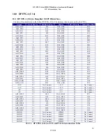
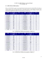
DPX FPGA LVDS Interface
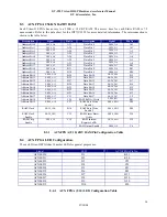
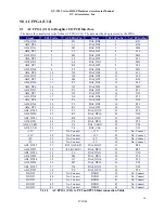
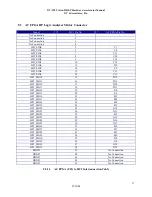
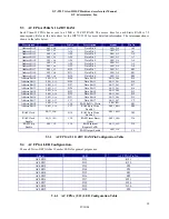
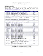
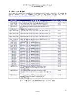
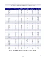
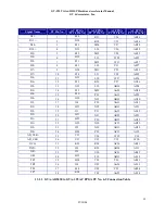
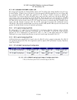
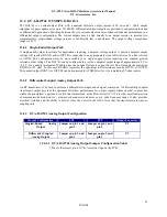
This is a 32 bit LVDS bus can be used to transfer data and control between the Virtex-II FGPA (U16) and two
external connectors. The 32-bit bus is broken into a 16-bit receiver bus and a 16-bit transmitter bus. Each of these
two buses has the appropriate termination resistors for the LVDS interface. LVDS_R designates a LVDS receiver
and LVDS_D designates a LVDS driver. The pin numbering does alternate rows.
Signal
DCX FPGA
(U16)
Pin No.
J4 No.
Signal
DCX FPGA
(U16)
Pin No.
J4 No.
LVDS_RN0 AB9
1
DGND
18
LVDS_RP0 AC9
2 LVDS_RN8 AF7
19
LVDS_RN1 AD6
3 LVDS_RP8 AG7
20
LVDS_RP1 AE6
4 LVDS_RN9 AL1
21
LVDS_RN2 AF2
5 LVDS_RP9 AK1
22
LVDS_RP2 AG2
6 LVDS_RN10 AH2
23
LVDS_RN3 AF3
7 LVDS_RP10 AJ2
24
LVDS_RP3 AG3
8 LVDS_RN11 AJ4
25
LVDS_RN4 AF5
9 LVDS_RP11 AK4
26
LVDS_RP4
AG5 10
LVDS_RN12
AK2 27
LVDS_RN5
AE8 11
LVDS_RP12
AL2 28
LVDS_RP5
AD8 12
LVDS_RN13
AH6 29
LVDS_RN6 AH1
13 LVDS_RP13 AJ5
30
LVDS_RP6 AJ1
14 LVDS_RN14
AE11
31
LVDS_RN7 AG4
15 LVDS_RP14 AF11
32
LVDS_RP7 AH5
16 LVDS_RN15 AF10
33
DGND 17
LVDS_RP15
AG9 34
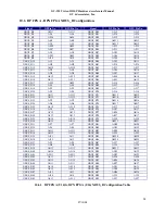
11.4.1
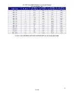
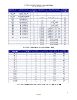
DPX FPGA LVDS Bus Interconnection Table for J6
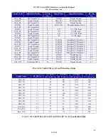
Signal
DCX FPGA
(U16)
Pin No.
J5 No.
Signal
DCX FPGA
(U16)
Pin No.
J5 No.
LVDS_DN0 AE4
1
DGND
18
LVDS_DP0 AF4
2 LVDS_DN8 AA5
19
LVDS_DN1 AD5
3 LVDS_DP8 AB5
20
LVDS_DP1 AE5
4 LVDS_DN9 AA1
21
LVDS_DN2
AB10 5
LVDS_DP9
AB1 22
LVDS_DP2 AC10
6 LVDS_DN10 Y7
23
LVDS_DN3 AC8
7 LVDS_DP10 AA8
24
LVDS_DP3 AB8
8 LVDS_DN11 AA4
25
LVDS_DN4 AC4
9 LVDS_DP11 AB4
26
LVDS_DP4 AD4
10 LVDS_DN12 W3
27
LVDS_DN5 AC3
11 LVDS_DP12 Y3
28
LVDS_DP5 AD3
12 LVDS_DN13 V1
29
LVDS_DN6 AB6
13 LVDS_DP13 V2
30
LVDS_DP6 AC6
14 LVDS_DN14 V7
31
LVDS_DN7 AA2
15 LVDS_DP14 W7
32
LVDS_DP7 AB2
16 LVDS_DN15 V5
33
DGND 17
LVDS_DP15
W5 34
11.4.2
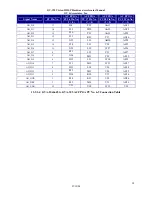
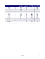
DPX FPGA LVDS Bus Interconnection Table for J7


