4
STEP 2
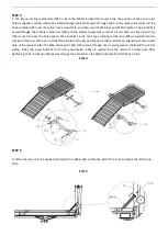
2. Place the bottom bracket (1#) on the bottom of the carrier frame (5#) and position the square hole. The M10*45mm
ring screw (4#) is then passed through the bottom bracket (1#) and the carrier frame (5#) and the U clamp (2#). The
M10 lock nut (3#) is finally tightened. See FIG 2.
FIG 2
STEP 3
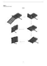
3. The spoon shaped fixed plate (6#) protrusion side is faced to the inside of the carrier frame (5#) and is mounted on
the left of the carrier frame (5#), aligns two round holes, so that the M10 x 20mm ring screw (8#) passes through the
spoon shaped plate (6#) and the upper round hole of the carrier frame (5#) in turn, and then uses the M10 lock nut (3#)
to tighten. The button socket cap screw M10 x 25mm (7#) from the inside of the carrier frame (5#) through the carrier
frame (5#) and the spoon shaped fixed plate (6#) from the top of the second round holes, and then the M10 lock nut
(3#) tightened. Finally, the M10 x 20mm ring screw (8#) is made from the right side of the 10 flat washer (9#) and the
upper first round hole of the carrier frame (5#) from the right side of the carrier frame (5#), and the M10 lock nut (3#) is
tightened. See FIG 3.
FIG 3
FIG: 1
Note: After complete the installation, we
must ensure that the 4 bolts are on the
same straight line. This is the correct way
of installation.
The head of the
ring screw
(4#) goes towards the
outer side of the
carrier
frame (5#).
Содержание 712140
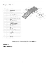
Страница 6: ...6 STEP 6 Folding steps See FIG 6 FIG 6...


