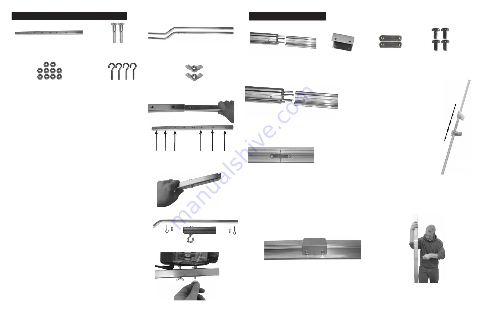
Start
by inserting the 2 crossbar ends into the cross-
bar splint.
Next
align the holes in the crossbar splint with the holes
in the crossbar. There are 3 holes in each side of the
splint to accommodate different crossbar widths. You
must use the same holes in each side so the crossbar
ends span an equal distance from the center of the
splint (Fig 4-1).
After
inserting the 2 crossbar ends into the crossbar
splint secure them using the 2 - 1/4” x 1 1/2” crossbar
to splint screws and 2 of the 1/4” hex nuts (Fig 4-2).
Next
install the 4 - lamp hanging eye screws with the
remaining 1/4” hex nuts (Fig 4-3). There are two sets
of holes on each end to accommodate different light
widths. Note: As in the LightRail 5 logo you can see
the crossbar ends are bent. If you have a particularly
high ceiling you may want to hang the crossbar with
the bends down opposite the logo. This you will need
to decide so the 1/4” eye screws are mounted facing
the right way.
Now
that the crossbar is assembled it can be mounted
to the Drive Motor. Locate the 2 holes in the center of
the crossbar splint. Slide them over the two 1/4” screws
protruding from the bottom of the Drive Motor and fas-
ten it using the 2 - 1/4” wing nuts (Fig 4-4). Be sure
to tighten the wing nuts until the 1/4” screws on the
bottom of the Drive Motor begin to protrude from the
bottom of the wing nuts (Fig 4-4).
STEP FOUR: INSTALLING THE CROSSBAR
4 - Lamp Hanging
Eye Screws
1 - Crossbar splint
2 - 1/4” Wing Nuts
2 - Crossbar ends
2- 1/4” x 1 1/2”
Crossbar to Splint Screws
10 -1/4” Hex Nuts
Tools you will need:
7/16” wrench, pliers
Fig 4-1
Crossbar Width Adjustment Holes
Fig 4-4
Fig 4-3
Fig 4-2
STEP ONE: RAIL ASSEMBLY
Start
by matching ends of Rail halves
with arrows. While making sure the
alignment pins line up with their cor-
responding holes, push the two Rail
halves together (Fig 1-1); if needed
you can tap the Rail end on the floor to
assist in pushing the Rail halves all the
way together (Fig 1-2).
Next
insert one slide nut in the slide nut channel
on each side of the Rail. Push them towards the
middle until they cover the joint where the 2 Rail
halves meet (Fig 1-3).
Last
slide the Rail coupler over the top of the Rail and start each of the 4 - #10 machine
screws into the threaded holes in the slide nuts (Fig 1-4). Tighten them just until they are
snug, then stand the Rail on its end and torque the screws tight while pushing down on the
Rail (Fig 1-5).
Tools you will need: Phillips head screwdriver
1 - Rail Coupler
2 - Slide Nuts
2 - Rail Halves
4 - #10 x 3/8”
Machine Screws
Fig 1-3
Fig 1-5
Fig 1-4
Fig 1-2


