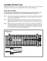
background image

2

Illustration A

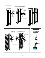
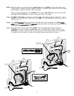
Installing The Gate Lock

Receiver pin hole and lock slot must line up.
Check alignment with pin out of receiver.

Lock and receiver must be level
and aligned with opener.
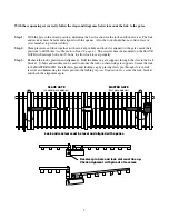
Step 1:

   With the gate in the closed position, determine the best location for the lock and lock receiver. The lock 

and receiver must be level and aligned with the opener.  Also, the lock should have a solid surface or 

cross member to provide stability.
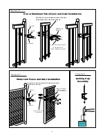
Step 2

:  Clamp receiver and lock together (with receiver pin hole and lock slot aligned) against the gate post, 

mark their positions to drill receiver holes (

see Illustration B and C, page 3

).  The receiver must be 

mounted with carriage bolts, not U-bolts, to allow lock to seat properly.  Fasten the receiver to the gate 

post.

Step 3:

  Recheck the lock's position and alignment, then mark its position for drilling holes.  Drill the holes on 

gate supports through the slots in the lock bracket.  U-bolts and saddles can be used to mount the lock 

on chain link gate supports. Secure the lock to the gate.  Install clevis pin and locking cap by placing 

clevis pin through slots in lock receiver and hammering the clevis pin into the locking cap (

see Illustra-

tion D

), secure the lock bracket and check the alignment again.
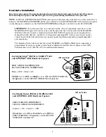
NOTE:

 The Automatic Gate Lock can be installed on single and dual gate systems. Use the appropiate 

instructions for the system you have - SINGLE GATE (below) or DUAL GATES (page 4).

Disconnect gate opener by removing hairpin clip and clevis pin from the gate bracket end of the opener.  

Disconnecting the opener will allow the gate to swing freely during installation of the gate lock.

Single Gate Installation

Содержание RB909

Страница 1: ...This manual shows two examples of the most common installations and should provide insight into most other applications If you have any questions during installation please call 850 575 4144 for techn...

Страница 2: ...rts 1 Mounting The Lock and Lock Receiver 2 Connecting the Control Boards Once you have the necessary mounting hardware you can begin the installation Before You Start For the GTOAutomatic Gate Lock t...

Страница 3: ...n the receiver to the gate post Step 3 Recheck the lock s position and alignment then mark its position for drilling holes Drill the holes on gate supports through the slots in the lock bracket U bolt...

Страница 4: ...es in fence post Illustration B Iron or Aluminum Tube Fence and Gate Installation Illustration C Chain Link Fence and Gate Installation Illustration D Locking Cap Assembly Clevis Pin Receiver Locking...

Страница 5: ...gate sequencing The diagrams below will show how most dual GTO PRO and Mighty Mule gate sequencing is programmed If your gate opener control board is different form these shown please contact GTO Tech...

Страница 6: ...eck the lock s position and alignment Drill the holes on gate supports through the slots in the lock bracket U bolts and saddles can be used to mount the lock on chain link gate supports Secure the lo...

Страница 7: ...ber to check the alignment and mark positions before drilling holes in fence post Illustration F Clevis Pin Receiver Locking Cap GTO Automatic Gate Lock Carriage bolts washers and nuts not provided si...

Страница 8: ...the Wire Connector Place the WHITE wire from the lock board inside the blocked channel on the Wire Connector If the gate opens into the property pull to open place the BLACK wire from the opener power...

Страница 9: ...Terminal 3 on lock board Attach RED wire to Terminal 4 on lock board see Wiring Chart on page 7 Step 6 Attach RED lock board battery lead wire to the double spade tongue terminal with the RED control...

Страница 10: ...attery lead wire to the double spade tongue terminal with the RED control board lead wire Attach the BLACK lock board battery lead wire to the double spade tongue connector with the BLACK control boar...

Страница 11: ...tion 2000 BLACK RED R E D WHITE B L A C K Wiring the Lock to Mighty Mule FM 700 702 and GTO PRO 1000 and 2000 Gate Opener Control Boards with Terminal Strips 15 15 D E R K L B N R G G R O L B U D E R...

Страница 12: ...ll To Open gates or BLK for Push To Open RED Wire To Battery Positive Terminal RED Wire From Lock BLACK Wire From Lock BLACK Wire To Battery Negative Terminal 1 2 3 4 5 Lock Board Double Spade Connect...

Страница 13: ...nufacturer will not be responsible for any charges or damages incurred in the removal of the defective parts for repair or for the reinstallation of those parts after repair This warranty shall be con...

Отзывы: