- 6 -
HMM 470 / HMM 470 OIRT / HMS 470
3
Installation
– Ensure the head-end station is mounted so it will not be able to vibrate.
Avoid, for example, mounting the head-end station onto a lift shaft or any
other wall or floor construction that vibrates in a similar way.
– Before installing or changing a module, switch off the head-end station or
unplug the power cable from the mains power socket.
Take measures to protect against ESD!
•
Open the housing of the
head-end station in accordance with the assembly
instructions for the STC 160.
3.1 Installing the modulator module
– Always position modules which belong together next to each other. The
modulator module must be installed to the right of the digital module or an
add-on module.
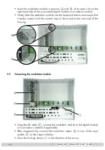
– When installing a module, make sure that it is inserted in the long numbered
grooves in front of the contact strip on the board at the rear wall of the hous-
ing.
The shorter, not numbered grooves without contact strip on the board at the
rear wall of the housing are for add-on modules only.
•
Open the housing of the
head-end station in accordance with the assembly
instructions for the STC 160.
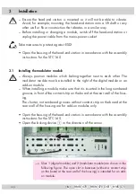
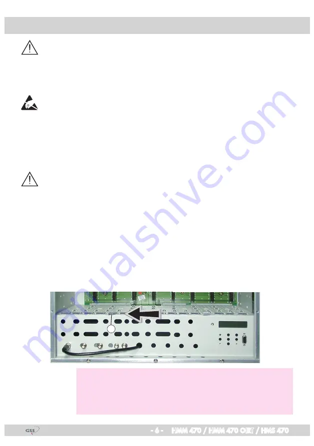
• Open the locking device
1
in the direction of the arrow.
1
—> Slots 1 (digital module) and 2 (modulator module) are shown in the
following figure. The open slot in between (without a contact strip
on the board at the rear wall of the housing) is intended for an add-
on module.
Содержание HMM 470
Страница 19: ... 19 HMM 470 HMM 470 OIRT HMS 470 ...
Страница 20: ... 20 HMM 470 HMM 470 OIRT HMS 470 ...
Страница 21: ... 21 HMM 470 HMM 470 OIRT HMS 470 ...


