

HT E11 / E12 Ethernet Terminal Instruction Manual
6
2. INSTALLATION INFORMATION
2.1 Installation Information
1.
Secure the device to a suitable place in the panel. (Suitable for rail
mounting.)
2.
Make a supply connection to the terminal named “POWER 220 V AC”.
Make sure there is no power in the cables in the meanwhile.
3.
The connection with the device to be communicated:
a.
Electric Meter / Optical Port: See. Figure 3.1; 3.2
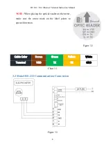
b.
Electric Meter /RS-232: See. Figure 3.3
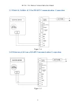
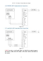
c.
Electric Meter / RS-485: See. Figure 3.4; 3.5; 3.6; 3.7; 3.8; 3.9
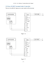
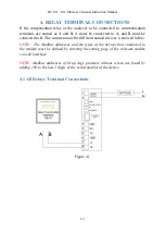
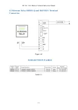
d.
Modbus Device (Relay, analyzer, etc.) / RS-485: See. Figure 4.1;
4.2
4.
Connect the Ethernet cable to the Ethernet input.
5.
Operate the device by energizing after checking all the connections for the
last time.
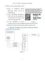
6.
After a while, by entering SmartPower Energy Monitoring System, you
can check whether your device is sending data or not. If you have no
internet access in the field, you can get help from our technical support
line.
NOTE:
1.
If the link LED on the Ethernet socket is not on or the IP LED is steadily
on red, make sure there is a healthy internet connection on the Ethernet
cable.
2.
If more than one meter is to be connected via RS-485, the technical
support line must be called, and the serial numbers of the meters must be
defined to the system.
3.
Modbus devices to be read via RS-485 must be defined to the system. The
Modbus addresses of all the devices on the same line must be different.
For this purpose, you may need to enter the menu of the related device
and change the Modbus address.