background image


1


Overview 

1.1


IR Speed Dome Overview 

Note: 

The figures below are for reference only, refer to the actual product as the standard. 

1.1.1


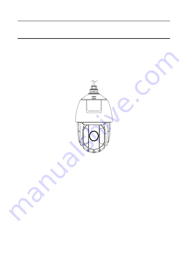
Overview of the IR Speed Dome 


Figure 1-1


Overview of the IR Speed Dome 

1.2


Cable Interfaces 

The cable interfaces of the speed dome are shown in Figure 1-2. The cables are 
distinguished by different colors. Refer to the labels attached on the cables for 
identification.


Notes: 


Make sure the speed dome is power-off before you connect the cables. 

Содержание GD-CI-AP2747P

Страница 1: ...WWW GRUNDIG SECURITY COM GD CI AP2747P Network PTZ Dome Camera Quick Guide ...

Страница 2: ...a or documentation in connection with the use of this product even if our company has been advised of the possibility of such damages Regarding to products with internet access the use of the product shall be wholly at your own risks Our company shall not take any responsibilities for abnormal operation privacy leakage or other damages resulting from cyber attack hacker attack virus inspection or ...

Страница 3: ...ntilation openings if there are any Ensure that the product is well ventilated to prevent any over heating Do not subject the device to physical shock or drop the product If the product uses batteries please use a battery type that is recommended by the manufacturer Improper use or replacement of the battery may result in the hazard of explosion Do not use any accessories that are not recommended ...

Страница 4: ...ersible damage to the camera can be caused by a strong light Do not expose the sensor of the product to laser beams as this may damage the sensor If the product supports IR you need to take some precautions to prevent IR reflection Do not install the product close to reflective surfaces of objects as this may cause reflection If the product has a dome cover please remove the protection film only a...

Страница 5: ...6 2 Installation 7 2 1 Installing the IR Speed Dome 7 2 1 2 Wall Mounting 7 3 Setting the Speed Dome over the LAN 10 3 1 Wiring 10 3 2 Activating the Camera 10 3 2 1 Activation via Web Browser 11 3 2 2 Activation via Grundig IP Finder Tool 11 3 3 Modifying the IP Address 13 4 Accessing via Web Browser 14 4 2 Initializing the Memory Card 15 ...

Страница 6: ...verview of the IR Speed Dome Figure 1 1 Overview of the IR Speed Dome 1 2 Cable Interfaces The cable interfaces of the speed dome are shown in Figure 1 2 The cables are distinguished by different colors Refer to the labels attached on the cables for identification Notes Make sure the speed dome is power off before you connect the cables ...

Страница 7: ...Power Cord Figure 1 2 Cable Interfaces 1 3 Alarm Output Alarm output is shown in Figure 1 3 Relay Output OUT n DC OUT n Direct load Relay Output OUT n OUT n DC 30V 1A Power Supply GND Output 220V AC FireWire Zero Line JQC 3FG Relay 10A 250VAC Figure 1 3 Alarm Output ...

Страница 8: ...les otherwise the waterproof performance is affected Figure 2 1 Do Not Drag the Cables 2 1 Installing the IR Speed Dome 2 1 2 Wall Mounting Notes For cement wall you need to use the expansion screw to fix the bracket The mounting hole of the expansion pipe on the wall should align with the mounting hole on the bracket For wooden wall you can just use the self tapping screw to fix the bracket Make ...

Страница 9: ...1 Get the bracket and screws from the packing box as shown in Figure 2 3 Figure 2 3 Wall Mounting Bracket 2 Drill four screw holes in the wall according to the holes on the bracket and then insert four M8 expansion screws into the mounting holes 3 Attach the gasket and the bracket to the wall by aligning the four screw holes on the bracket with four expansion screws on the wall 4 Secure the bracke...

Страница 10: ...he corresponding cables 3 Loosen the lock screws on the bracket 4 Align the speed dome with bracket and rotate it to the bracket counterclockwise or clockwise tightly as shown in Figure 2 6 Push Rotate Lock Screw Figure 2 6 Align to the Bracket 5 Tighten the two lock screws with the wrench to secure the speed dome and the bracket 4 Remove the protective film on the bubble after the installation is...

Страница 11: ...se strengthen your own protection If the product does not work properly contact your dealer or the nearest service center for help 3 1 Wiring Connect the camera to the network according to the following figures Figure 3 1 Connecting Directly Figure 3 2 Connecting via a Switch or a Router 3 2 Activating the Camera You are required to activate the camera first by setting a strong password for it bef...

Страница 12: ...ndig IP Finder Tool to search the IP address Figure 3 3 Activation Interface Web 3 Create a password and input the password into the password field STRONG PASSWORD RECOMMENDED We highly recommend you create a strong password of your own choosing Using a minimum of 8 characters including at least three of the following categories upper case letters lower case letters numbers and special characters ...

Страница 13: ...eate and input the new password in the password field and confirm the password STRONG PASSWORD RECOMMENDED We highly recommend you create a strong password of your own choosing Using a minimum of 8 characters including at least three of the following categories upper case letters lower case letters numbers and special characters in order to increase the security of your product And we recommend yo...

Страница 14: ... as an example to introduce the IP address modification Steps 1 Run the Grundig IP Finder tool 2 Select an active device 3 Change the device IP address to the same subnet with your computer by either modifying the IP address manually or checking the checkbox of DHCP Figure 3 4 Modify the IP Address 4 Input the admin password and click Modify to activate your IP address modification The batch IP ad...

Страница 15: ...eps 1 Open the web browser 2 In the browser address bar input the IP address of the network camera and enter the login interface Note The default IP address is 192 168 1 100 You are recommended to change the IP address to the same subnet with your computer 3 Input the user name and password The admin user should configure the device accounts and user operator permissions properly Delete the unnece...

Страница 16: ... 2 to step 4 to login Note For detailed instructions of further configuration refer to the user manual of network camera 4 1 Initializing the Memory Card Steps Check the memory card status by tapping on the Storage Status in the Device Settings interface If the memory card status displays as uninitialized tap to initialize it The status will then change to Normal You can then start recording any e...

Отзывы: