background image

GRUNDIG Service

 1 - 3

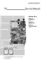
Châssis / Chassis 12.6

Partie générale / General Section

F

Partie générale

Information générale

Avant d'ouvrir le boîtier toujours débrancher la fiche secteur!

Variantes avec le châssis 12.5
Les appareils

DAVIO 37 P 37-2201 FR,
DAVIO 55 T 55-4201 FR/TOP,
ont déjà été fabriqués avec le châssis 12.5.

Pour ces appareils, utiliser le Service Manual 720100442000.
Il est possible de distinguer les variantes à l’aide des numéros de
commande.

Câblage
Avant de défaire les lignes, spécialement les lignes de masse, il faut
repérer les connexions à chaque ensemble fonctionnel, comme par
exemple le châssis principal, le C.I. Interrupteur secteur, le C.I.
Commande, le C.I. Tube cathodique, le bloc de déviation, les haut-
parleurs, etc.
A la fin d'une intervention, les connexions doivent être remises dans
leur position d'origine afin d'éviter par après d'éventuelles défaillances
ou perturbations.

Cable dereseau
Ces appareils ne peuvent être utilisés qu ' avec un cable de connecion
original de réseau avec bobine antiparasite intégré dans la fiche de
secteur. Ce câble de réseau empêche des perturbations de réseau et
est partie de l'autorisation d'appareil. Si nécessaire commandez
uniquement le cable de réseau selon la liste de pièces détachées.

Information pour la maintenance

Tube d‘image défectueux:
Si le tube image est défectueux, veuillez envoyer l'appareil à:

Service Note

Defective CRT:
In the event of a defective picture tube please send your TV set to:

GB

General Section

General Notes

Before opening the cabinet disconnect the mains plug!

Variants with Chassis 12.5
The sets

DAVIO 37 P 37-2201 FR,
DAVIO 55 T 55-4201 TOP/FR
are already produced with chassis 12.5. For these

sets please use the Service Manual 720100442000. The variants are
distinguishable by the order numbers.

Wiring
Before disconnecting any leads and especially the earth connecting
leads observe the way they are routed to the individual assemblies like
the chassis, mains switch panel, keyboard control panel, picture tube
panel, deflection unit, loudspeaker and so on.
On completion of the repairs the leads must be laid out as originally
fitted at the factory to avoid later failures or disturbances.

Mains Cable
The TV receiver must only be operated with an original mains connecting
cable with an interference suppressor choke integrated in the mains
plug.This mains cable prevents interference from the mains supply and
is part of the product approval. For replacement please order exclusively
the mains connecting cable specified in the spare parts list.

Information sur la sécurité

L'émission de rayons X produite par les téléviseurs est conforme aux
spécifications de l'Office Fédéral de Physique et de Technique
publiées le 8 Janvier 1987 (Physikalisch-Technische Bundesanstalt).
La haute tension induite dans le tube et de ce fait l'émission de rayons
X dépend de la précision du réglage de la tension d'alimenB.
Après tous travaux de maintenance dans l'alimentation ou dans la
déviation horizontale il y a lieu de contrôler la haute tension et au
besoin de reprendre le réglage.
Les circuits de protection de l'appareil ne doivent être mis hors
service que pendant un temps limité afin d'éviter tous dommages sur
le châssis ou sur le tube.
En cas de remplacement du tube il est recommandé d'utiliser
exclusivement le type de tube spécifié dans la liste de pièces
détachées.

Safety Advice

The X-radiation developing in the sets conforms to the X-radiation
Regulations (January 8, 1987), issued by the Physikalisch-Techni-
sche Bundesanstalt (federal physiotechnical institution).
The high tension for the picture tube and thus the developing X-
radiation depends on the precise adjustment of the +B power supply.
After every repair of the power supply unit or the horizontal deflection
stage it is imperative that the EHT for the picture tube is checked and
re-adjusted if necessary.
To avoid consequential damages to the chassis or the picture tube
the integrated protective circuits are allowed to be put out of
operation only for a short time.
When replacing the picture tube use only the types specified in the
spare parts lists.

GRUNDIG AG

CENTRAL SERVICE

- TOR 8 -

BEUTHENER STR.55
D-90471 NÜRNBERG

Содержание DAVIO 37 P 37-2201

Страница 1: ...aire n cessaire pour la maintenance Additionally required Service Documents for the Complete Service Service Manual Service Training TV Service Manual Chassis 12 6 DAVIO 37 P 37 2201 FR GBA0502 DAVIO...

Страница 2: ...Table of Contents Page General Section 1 3 1 12 General Notes 1 3 Safety Advice 1 3 Service Note 1 3 Tables of Norms and Channels 1 4 Technical Data 1 7 Operating Hints DAVIO 55 T55 4201 FR TOP only F...

Страница 3: ...keyboard control panel picture tube panel deflection unit loudspeaker and so on On completion of the repairs the leads must be laid out as originally fitted at the factory to avoid later failures or d...

Страница 4: ...50 C 51 703 25MHz 711 25MHz 52 53 54 55 C 52 C 53 719 25MHz 727 25MHz C 54 C 55 735 25MHz 743 25MHz 56 57 58 59 C 56 C 57 751 25MHz 759 25MHz C 58 C 59 767 25MHz 775 25MHz 60 61 62 63 C 60 C 61 783 2...

Страница 5: ...Hz 380 75MHz Y S 62 392 75MHz Interbande Special Channels Norme L L Norm L L Ecart son image Sound vision spacing 6 5MHz Pas des canaux Channel bandwidth 10 5MHz Nom Name S 70 S 71 S 72 N canal Channe...

Страница 6: ...dwidth 8MHz Nom Name S 21 S 22 S 23 N canal Channel no S 21 Fr quence image Vision carrier frequency 303 25MHz S 22 S 23 311 25MHz 319 25MHz S 24 S 25 S 26 S 27 S 24 S 25 327 25MHz 335 25MHz S 26 S 27...

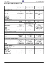
Страница 7: ...sung 90 50Hz 99 2 AV PLL fr quence synthesizer Tuning UHF VHF PLL frequency synthesizer tuning UHF VHF 99 2 AV B G L L PAL SECAM via AV NTSC 4 43MHz B G L L PAL SECAM via AV NTSC 4 43MHz Mono 5W ront...

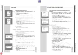
Страница 8: ...l Section 1 8 Mode d emploi Ce chapitre contient des extraits du mode d emploi Pour toutes informations suppl mentaires veuillez vous r f rer au mode d emploi sp cifique chaque appareil dont le num ro...

Страница 9: ...GRUNDIG Service 1 9 Partie g n rale General Section Ch ssis Chassis 12 6...

Страница 10: ...ALPS Version du tuner version of tuner PHILIPS P SONIC AGC TEMIC voir alignement see adjustment Version du tuner version of tuner Version du tuner version of tuner x Version du tuner version of tuner...

Страница 11: ...nement see adjustment R DRV B DRV voir alignement see adjustment voir alignement see adjustment Menu 4 touche bleue button blue SCRN SECBL voir alignement see adjustment voir alignement see adjustment...

Страница 12: ...usine par la touche Dialog Center Service OK R glages d usine puis m moriser par OK 8 Num ro de programme maximal point d inversion Lorsque la fonction ATS est termin e le point d inversion est ajout...

Страница 13: ...teuse son d sactiv e via l antenne Canal 32 70 1dB V Activerlemodedeservice choisirlemenu1 touche rouge A l aide de ou s lectionner AGC A l aide de ou s lectionner 2 AGC Activer le mode de service cho...

Страница 14: ...CUT A l aide de la touche ou s lectionner R CUT A l aide de la touche ou s lectionner B CUT A l aide de la touche ou s lectionner R DRV A l aide de la touche ou s lectionner B DRV Seulement n cessaire...

Страница 15: ...nd Tuner Colour video generator Feed in a colour scale with switched off sound carrier via the aerial channel 32 70 1dB V Start the Service Mode call up the dialog line AGC via menu 1 red button with...

Страница 16: ...with button or Only necessary if deadjusted Adjust according to the test pattern using button or Adjust according to the test pattern using button or Adjust according to the test pattern using button...

Страница 17: ...lectriques Layout of PCBs and Circuit Diagrams GRUNDIG Service 3 1 TV marche on Standby TV marche on Standby m u i v x Oscillogrammes du ch ssis Oscillograms Chassis Board Circuit imprim s et sch mas...

Страница 18: ...Circuit imprim s et sch mas lectriques Layout of PCBs and Circuit Diagrams Ch ssis Chassis 12 6 3 2 GRUNDIG Service y u v x y m i v x y m u i v...

Страница 19: ...ut of PCBs and Circuit Diagrams GRUNDIG Service Ch ssis Chassis 12 6 Circuit imprim s et sch mas lectriques Layout of PCBs and Circuit Diagrams 3 3 3 4 C I Ch ssis Principal Chassis Board C te composa...

Страница 20: ...it Diagrams Ch ssis Chassis 12 6 GRUNDIG Service Circuit imprim s et sch mas lectriques Layout of PCBs and Circuit Diagrams Ch ssis Chassis 12 6 3 5 3 6 C I Ch ssis Principal Chassis Board C te soudur...

Страница 21: ...0p 500V C517 H LIN L502 HORIZONTAL X502 4 3 2 1 FBT TR501 8 4 1 11 9 7 6 2 5 10 3 G2 FOCUS EHT 6 8n 1 5kV C513 9V R521 47u 35V C512 2 2uH L501 27R 0 5W R518 4 7k R519 BU808DFI T504 82R 3W R517 10k R51...

Страница 22: ...SW402 SW401 1k R413 VDD_2 5V 1N4148 D404 10n C409 9V 47n C412 10k R419 2 2k R420 3 3V 1k R423 10k R418 BC848 T403 220p C413 1k R466 10n C414 10k R427 10k R433 10n C417 BC848 T404 BC848 T405 MULTIMEDIA...

Страница 23: ...6 VERT_OUT 45 SAW TOOTH 44 AUD_ DECOUPLING 43 AFC1 42 HORIZ_OUT 41 H_VCC 6 3V 40 3 58 39 HOR_SYNC 38 VID_IN_SYNC 37 C APC2 36 VIDEO_OUT 35 VCC 4 7V 34 EXT_VIDEO_OUT 33 VCC 32 EXT_AUDIO_OUT 31 BLK LEVE...

Страница 24: ...R720 220R opt R719 CRT X701 5 4 3 2 1 SMPS AQUA G2 CRT X703 3 2 1 155V crt 100n 250V C708 2 2n C707 1 5K R714 1 5K R708 1 5K R704 9V_ 9V_ 2 7k R716 crt 100R R718 390p C706 crt 470R R717 155V 15k 1W R7...

Страница 25: ...0604 S 725511823600 DIODE RF2007 D 00606 S 725511823600 DIODE RF2007 D 00607 S 830956550700 DIODE RGP10J 1N4937 MOT G D 00609 S 759550453500 DIODE RGB15D D 00610 S 759880511100 DIODE RGP15J D 00701 83...

Страница 26: ...nual Sicherheit Mat Nummer 720108000000 sowie zus tzlich die eventuell abwei chenden landesspezifischen Vorschriften II y a lieu d observer les recommandations et les prescriptions de s curit de I Ins...

Страница 27: ...23600 DIODE RF2007 D 00606 S 725511823600 DIODE RF2007 D 00607 S 830956550700 DIODE RGP10J 1N4937 MOT G D 00609 S 759550453500 DIODE RGB15D D 00610 S 759550455400 DIODE RGP30MS D 00701 830921503300 DI...

Отзывы: