GRUNDIG Service
2 - 12
CUC 6460 / 6469
Schaltungsbeschreibung / Circuit Description
sten Bildwert innerhalb einer bestimmten Zeitspanne, die Kennlinien-
steilheit erhöht wird. Dadurch wird im dunklen Bildbereich die Grada-
tion verbessert. Der "Black-level-stretcher“ wird aktiviert, indem
IC5040-(2) auf dessen Betriebsspannung gelegt wird und deaktiviert,
wenn er auf Masse gelegt wird.
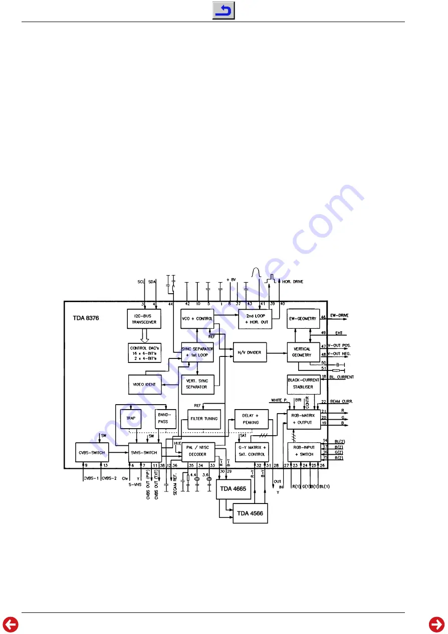
Das Y-Signal muß abschließend noch um etwa 350ns in der CTI-
Schaltung IC5160, TDA4566, verzögert werden, um die "Laufzeit“ der
Chromaversteilerung auszugleichen. Am TDA8376-(27) steht es dann
zur Wiedergewinnung der Primärfarben in der Matrix zur Verfügung.
5.6 RGB-Einblendung und Bildrohransteuerung
Am Ausgang der Matrix, in der die Farbsättigung eingestellt wird,
stehen die Primärfarben RGB an. An den zwei nacheinander angeord-
neten Umschalteinheiten stehen zunächst die externen RGB-Signale
(von Peribuchse 1 oder 2) und dann die internen RGB-Signale (Text,
Menü zur Benutzerführung und PIP) an. Diese werden je nach Schalter-
stellung an den Ausgang des Decoders geschaltet. Beide Schalter-
einheiten sind mittels der zugehörigen Schaltspannung statisch oder
dynamisch nutzbar. In bestimmten Programmstellungen wird die
Einblendmöglichkeit von externen Quellen von der Software nicht
zugelassen. Durch die serielle Anordnung der Schalter ist auch bei
externem RGB-Betrieb ein Vorrang der internen RGB-Signale und
damit vor allem der menüorientierten Gerätesteuerung gewährleistet.
Die letztendlich zur Verfügung stehenden RGB-Signale werden in
einer weiteren Stufe bezüglich Helligkeitseindruck und Kontrast über
den I
2
C-Bus beeinflußt. Anschließend werden die drei Ausgangs-
amplituden getrennt in der Verstärkung variiert, um den Weißwert des
Bildes auf Sollwert abzugleichen. Diese Justage der Farbtemperatur
wird im Fertigungsprozeß ermittelt und abgespeichert.
Der DC-Arbeitspunkt der Ausgangsstufen des TDA8376 und damit der
DC-gekoppelten Videoendstufen zur Bildrohransteuerung wird durch
einen Regelkreis ermittelt, der die Kathodenströme im Sperrpunkt
mißt (Meßeingang TDA8376-(18)) und auf einen Wert von 10
µ
A
ausregelt. Die früher notwendigen externen Speicherkondensatoren
sind vollständig integriert, mit deren Hilfe das Meßergebnis über ein
Halbbild gespeichert wird.
picture. The "black-level-stretcher“ is activated by switching IC5040-(2)
to its operating voltage and it is deactivated by applying ground
potential.
Finally, the Y-signal must be delayed by approximately 350ns in the
CTI circuit IC5160, TDA4566, to match the rise time of the chroma
signal. At TDA8376-(27) the signal is then available for the regenera-
tion of the primary colours in the matrix.
5.6 RGB Display and Control of the Picture Tube
The primary colours RGB are present at the output of the matrix which
is used to set the colour saturation. The external RGB signals (from
Peri socket 1 or 2) are applied to the first of the two following serially
arranged switching units, and the internal RGB signals (text, menu for
guiding the user, and PIP) are applied to the second switching unit.
These signals are passed on to the output of the decoder according to
the setting of the switches. Both switching units can be used statically
or dynamically by means of the appropriate switching voltage. In
certain programme positions the software does not allow to display
data from external sources. The serial arrangement of the switches
ensures that even with the external RGB mode, priority is given to the
internal RGB-signals, especially to the menu for operating the TV set.
Another stage is provided for controlling the brightness and contrast of
the selected RGB-signals via the I
2
-bus. Subsequently, the amplifica-
tion of the three output amplitudes is varied separately to set the white
value of the picture to the specified value. This colour temperature
adjustment is determined and stored during production at the factory.
The DC working point of the output stages of TDA8376 and thus of the
DC-coupled video output stages for driving the picture tube is deter-
mined by a control circuit which measures the cathode currents at the
cut-off point (measurement input TDA8376-(18)) and corrects the
current to a level of 10
µ
A. The previously necessary external storage
capacitors are completely integrated and are used to store the result
of the measurement as a half field.


