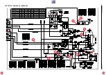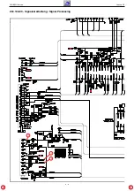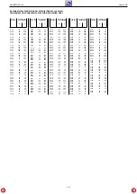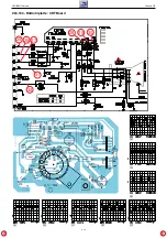
GRUNDIG Service
Chassis D5
2 - 1
Adjustment
Measuring instruments:
Digital voltmeter, colour video generator.
Service works after replacement or repair of the following modules:
– Power supply:
adjustment 1, 3
– Tuner / IF:
adjustment 2
– IC401 (EEPROM):
adjustment 2, 4…5
– CRT:
adjustment 3…5
– CRT panel:
adjustment 3, 5
– Deflection:
adjustment 4
1. Supply Voltage B+
– Digital voltmeter: D627 cathode.
– Programme: AV.
– Brightness control to minimum.
– Adjust
voltage B+
the values below the CRT with
VR601
.
Abgleich
Messgeräte:
Digitalvoltmeter, Farbbildgenerator.
Servicearbeiten nach Austausch bzw. Reparatur:
– Netzteil:
Abgleich 1, 3
– Tuner / ZF:
Abgleich 2
– IC401 (EEPROM):
Abgleich 2, 4…5
– Bildröhre:
Abgleich 3…5
– Bildrohrplatte:
Abgleich 3, 5
– Ablenkung:
Abgleich 4
1. Spannung B+
– Digitalvoltmeter: D627 Kathode
– Programm: AV
– Helligkeit auf Minimum.
–
Spannung B+
mit
VR601
entsprechend der Bildröhre einstellen:
Bildröhre
B+
A34 KPU02XXB
111V
A51ERF135X80
130V
A51ELD032X001
132V
2. AGC
– Service Mode aufrufen: Taste "
i
" drücken –> "
8500
" eingeben.
–
"AGC"
mit den Tasten
P+
/
P-
anwählen.
Mit den Tasten
Ǹ
/
Ƿ
Wert auf 35 einstellen.
–
TEST
mit den Tasten
P+
/
P-
anwählen.
Mit den Tasten
Ǹ
/
Ƿ
Wert auf 35 einstellen.
Bild mit 65 dB/
µ
V Antennenpegel auf Störungen, bzw. Kreuz-
modulation kontrollieren. Gegebenenfalls Wert/e erhöhen (z.B. 40).
– Service Mode beenden: Taste "
TXT
" drücken.
3. Screen
– Service Mode aufrufen: Taste "
i
" drücken –> "
8500
" eingeben.
–
SCRN
mit den Tasten
P+
/
P-
anwählen und mit den Tasten
Ǹ
/
Ƿ
auf
ON
stellen. Auf dem Bildschirm wird "BRI 00" angezeigt.
–
SCREEN
am Dioden-Splitt-Trafo TR501 so einstellen, dass
"BRI 00" gerade sichtbar ist.
– Mit den Tasten
Ǹ
/
Ƿ
auf Bild zurückschalten (
SCRN
wird auf
OFF
zurückgesetzt).
– Service Mode beenden: Taste "
TXT
" drücken.
4. Geometrie
– Geometrie-Testbild einspeisen.
– Service Mode aufrufen: Taste "
i
" drücken –> "
8500
" eingeben.
– Mit den Tasten
P+
/
P-
die gewünsche Bildgeometrie-Abgleich-
funktion aufrufen und mit den Tasten
Ǹ
/
Ƿ
die Geometrie einstellen:
– Bildmitte vertikal
VSLP
. Die untere Bildhälfte ist ausgeblendet.
Den Bildinhalt so einstellen, dass die Mittelline gerade nicht mehr
sichtbar ist.
– Zoom vertikal
VZOM
.
Bei 16:9 Geräten den Wert auf 35 einstellen.
Bei 4:3 Geräten VZOM so einstellen, dass der Kreis gerade den
Rand berührt. Gegebenenfalls VSLP nochmals korrigieren.
– Bildposition vertikal
VSHT
.
– Bildlinearität vertikal
SCOR
.
– Bildhöhe vertikal
VAMP
.
– Bildposition horizontal
HSHT
.
– Ost/West-Parabel 4:3
EWPW
.
– Ost/West-Trapez
EWT
.
– Ost/West-Parabel 16:9
EWP1
.
– Obere Ecken
EWCU
.
– Untere Ecken
EWCL
.
– Bildbreite bei 4:3 Geräten
EWW
.
– Schräglage (Parallelogramm) horizontal
HPAR
.
– Biegung horizontal
HBOW
.
– Service Mode beenden: Taste "
TXT
" drücken.
5. Weißabgleich / Cut off
– Testbild Grautreppe einspeisen.
– Service Mode aufrufen: Taste "
i
" drücken –> "
8500
" eingeben.
–
GRN
mit den Tasten
P+
/
P-
anwählen und mit den Tasten
Ǹ
/
Ƿ
auf
32
stellen.
–
RED
und
BLUE
jeweils mit den Tasten
P+
/
P-
anwählen und mit den
Tasten
Ǹ
/
Ƿ
so einstellen, dass der weiße Bildbereich
unbunt
ist.
Sollte sich der Weißwert nicht einstellen lassen, Wert für
GRN
korrigieren.
–
BLOR
und
BLOG
jeweils mit den Tasten
P+
/
P-
anwählen und mit
den Tasten
Ǹ
/
Ƿ
so einstellen, dass der dunkle Bildbereich
unbunt
ist.
– Service Mode beenden: Taste "
TXT
" drücken.
2. AGC
– Start the Service Mode: press button "
i
" –> enter "
8500
".
– Call up
AGC
with buttons
P+
/
P-
.
Adjust the value to 35 with buttons
Ǹ
/
Ƿ
.
– Call up
TEST
with buttons
P+
/
P-
.
Adjust the value to 35 with buttons
Ǹ
/
Ƿ
.
Check picture with 65db/
µ
V aerial level for interferences and cross-
modulation respectively. If necessary increase the values (e.g. 40).
– End the Service Mode: Press button "
TXT
".
3. Screen
– Start the Service Mode: press button "
i
" –> enter "
8500
".
– Call up
SCRN
with buttons
P+
/
P-
and switch
ON
with buttons
Ǹ
/
Ƿ
.
"BRI 00" is shown on screen.
– Adjust
SCEEN
control at the FPT TR501, that "BRI 00" is just visible.
– Switch back to screen with buttons
Ǹ
/
Ƿ
(
SCRN
is reset to
OFF
).
– End the Service Mode: Press button "
TXT
".
4. Geometry
– Apply a geometry test pattern.
– Start the Service Mode: press button "
i
" –> enter "
8500
".
– Call up the geometry function with buttons
P+
/
P-
and adjust the
geometry with buttons
Ǹ
/
Ƿ
:
– Vertical slope
VSLP
. The lower half part of the pattern is blanked.
Adjust picture so that the middle line of the pattern is cut.
– Zoom vertical
VZOM
.
For 16:9 sets, adjust the value to 35.
For 4:3 sets, adjust the circle of pattern just touches to the upper
an lower edges. Readjust the VSLP if required.
– Vertical shift
VSHT
.
– Vertical linearity
SCOR
.
– Vertical amplitude
VAMP
.
– Horizontal shift
HSHT
.
– East west parabola width 4:3
EWPW
.
– East west trapezium
EWT
.
– East west parabola width 16:9
EWP1
.
– Upper Corner
EWCU
.
– Lower Corner
EWCL
.
– Horizontal width for 4:3 sets
EWW
.
– Horizontal parallelogramm with
HPAR
.
– Horizontal bow
HBOW
.
– End the Service Mode: Press button "
TXT
".
5. White Balance / Cut off
– Apply a Grey Scale Test pattern.
– Start the Service Mode: press button "
i
" –> enter "
8500
".
– Call up
GRN
with buttons
P+
/
P-
and set it to 32 with buttons
Ǹ
/
Ƿ
.
– Call up
RED
and
BLUE
with buttons
P+
/
P-
and adjust the values
so that the white part of the picture becomes achromatic with buttons
Ǹ
/
Ƿ
. If white balance can not be adjusted properly change GRN
value.
– Call up
BLOR
and
BLOG
with the buttons
P+
/
P-
and adjust the
values so that the dark part of the picture becomes achromatic with
buttons
Ǹ
/
Ƿ
.
– End the Service Mode: Press button "
TXT
".
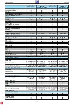
Bildröhre
B+
A33EKC01X01
111V
A33EKC02X01
111V
A34EAC01X06
111V
A34EJL02X31
111V
Bildröhre
B+
A34 KPU02XXB
111V
A51ERF135X80
130V
A51ELD032X001
132V
Bildröhre
B+
A33EKC01X01
111V
A33EKC02X01
111V
A34EAC01X06
111V
A34EJL02X31
111V
Содержание Chassis D5
Страница 6: ...Chassis D5 GRUNDIG Service 1 6 ...
Страница 8: ...Chassis D5 GRUNDIG Service 1 8 ...
Страница 16: ...GRUNDIG Service Chassis D5 3 2 ZL6 190 03 Netzteil Power Supply 1 3 4 2 1 2 3 4 ...
Страница 19: ...GRUNDIG Service Chassis D5 3 5 ZL6 190 03 Leiterplatte PCB ...
Страница 20: ...GRUNDIG Service Chassis D5 3 6 15 17 16 ZL5 190 03 Signalverarbeitung Signal Processing ...
Страница 23: ...GRUNDIG Service Chassis D5 3 9 Sicht auf Bestückungsseite View on Component Side ...
Страница 24: ...GRUNDIG Service Chassis D5 3 10 Ansicht auf Lötseite View on solder side ...
Страница 27: ...GRUNDIG Service Chassis D5 3 13 25 26 27 31 32 28 29 30 ZL5 194 Bildrohrplatte CRT Board ª º ...
Страница 34: ...4 2 GRUNDIG Service Chassis D5 Elegance 21 25 28 100 15 9 3 6 7 4 5 1 11 29 2 ...


