Eng
lish (US)
14
11. Maintenance and service
Flush the pump thoroughly with clean water before maintenance
and service. Rinse the pump parts in water after dismantling.
11.1 Annual maintenance
Pumps running normal operation must be checked every 3000
operating hours or at least once a year. If the dry solids content of
the pumped liquid is very high or sandy, check the pump at
shorter intervals.
Check the following points:
•
Power consumption
•
Motor oil level and oil condition
Check the condition of the oil and replace oil and shaft seal if
oil is contaminated. After replacement of the shaft seal, check
the oil level after one week of operation.
Use Shell Ondina X420 oil or similar type. See sections
.
•
Cable entry
Make sure that the cable entry is watertight and that the
cables are not sharply bent and/or pinched. See section
•
Pump parts
Check the impeller, pump housing, etc. for possible wear.
Replace defective parts. See section
.
•
Ball bearings
Check the shaft for noisy or heavy operation (turn the shaft by
hand). Replace defective ball bearings.
•
Grinder system or parts
In case of frequent choke-ups, check the grinder system for
wear. When worn, the edges of the grinding parts are round
and worn. Compare with a new grinder system.
11.2 Oil change
Motor oil quantities
The table states the quantity of oil in the oil chamber of SEG
pumps:
Draining of oil
1. Loosen and remove both oil screws to allow all the oil to drain
from the chamber.
2. Check the oil for water and impurities. If the shaft seal has
been removed, the oil will give a good indication of the
condition of the shaft seal.
Filling with oil
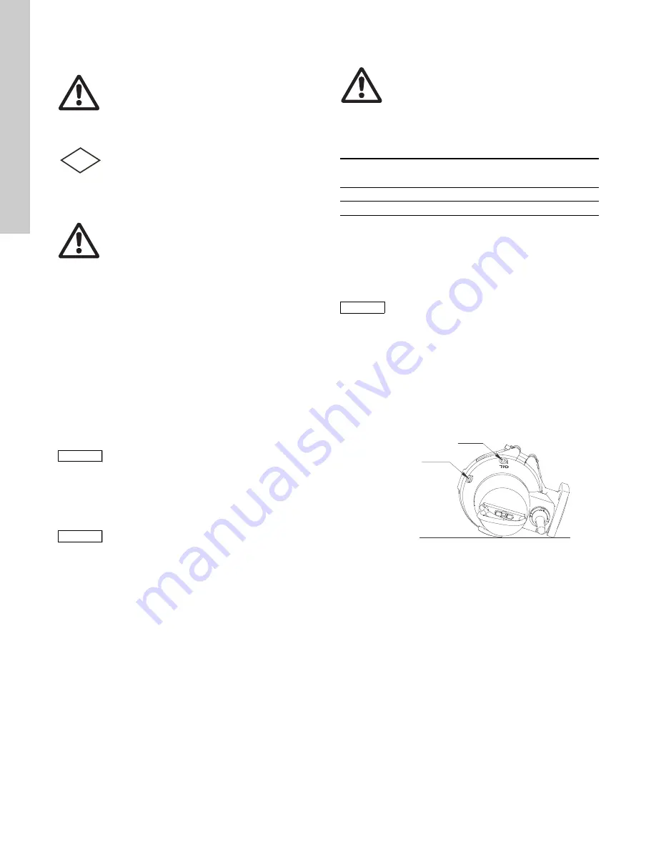
Pump in horizontal position:
1. Place the pump in such a position that it is lying on the stator
housing and the outlet flange and so that the oil screws are
pointing upwards. See fig.
2. Fill oil into the oil chamber through the upper hole until it starts
running out of the lower hole. The oil level is now correct.
3. Fit both oil screws using the packing material included in the
kit. See section
Fig. 11
Oil filling holes
Pump in vertical position:
1. Place the pump in upright position on a plane, horizontal
surface.
2. Fill oil into the oil chamber through one of the holes until it
starts running out of the other hole. For oil quality, see the
table above.
3. Fit both oil screws using the packing material included in the
kit. See section
Warning
Before starting work on the pump, make sure that the
fuses have been removed or the mains switch has
been switched off. Make sure that the power supply
cannot be accidentally switched on.
All rotating parts must have stopped moving.
Warning
Except for service on the pump parts, all other
service work must be carried out by Grundfos or a
service workshop authorized by Grundfos.
Warning
When loosening the screws of the oil chamber, note
that pressure may have built up in the chamber. Do
not remove the screws until the pressure has been
fully relieved.
Note
Note
Used oil must be disposed of in accordance with
local regulations.
Note
Note
A possible replacement of the cable must be carried
out by Grundfos or a service workshop authorized by
Grundfos.
FM
Warning
When loosening the screws of the oil chamber, note
that pressure may have built up in the chamber. Do
not remove the screws until the pressure has been
fully relieved.
Pump type
Oil in oil chamber
[oz (l)]
2.0 hp (1.5 kW)
6.0 (0.17)
3.0 to 5.5 hp (2.6 to 4.0 kW)
15.0 (0.42)
Note
Note
Used oil must be disposed of in accordance with
local regulations.
TM
06
57
48
03
16
Oil filling
Oil level
Содержание SEG Series
Страница 1: ...GRUNDFOS INSTRUCTIONS SEG 2 0 5 5 hp 60 Hz Installation and operating instructions ...
Страница 19: ...Appendix 19 Appendix Dimensional drawings Fig 1 One pump installation on auto coupling TM06 5743 0316 ...
Страница 20: ...Appendix 20 Fig 2 Free standing installation TM06 5742 0316 TM06 5745 0316 OIL OIL ...
Страница 24: ...Appendix 24 Fig 4 SEG L 2 0 Hp 1 5 kW TM05 8411 2313 ...
Страница 27: ...Appendix 27 Fig 2 Installation autonome TM02 5387 1310 TM02 5974 1310 ...
Страница 31: ...Appendix 31 Fig 4 SEG L pompe 2 0 CV 1 5 kW TM05 8411 2313 ...
Страница 34: ...Appendix 34 Fig 2 Instalación en posición libre TM02 5387 1310 TM02 5974 1310 ...
Страница 38: ...Appendix 38 Fig 4 SEG L 2 0 hp 1 5 kW TM05 8411 2313 ...
Страница 41: ...Grundfos companies ...


