Grundfos RF2 Скачать руководство пользователя страница 13

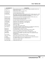
TROUBLE SHOOTING GUIDE (CONT.)

12

1

INDICATION

POSSIBLE CAUSE

CORRECTIVE ACTION

HW Desaturation

Accel/Decel rate set too short.
Torque Boost set too high.
Electrical noise in logic circuits.
Motor overloaded.

Lengthen Accel/Decel rate.
Reduce torque boost value.
Check for proper grounding of power wiring and shielding of signal wiring.
Verify proper sizing of control and motor or reduce motor load.

HW Power
Supply

Power supply malfunctioned.

Check internal connections.
Replace logic power board.

HW Ground Fault

Output current (motor current)
leakage to ground.

Disconnect wiring between control and motor. Retry test.  
If GND FLT is cleared, reconnect motor leads and retry the test.  Repair

 motor if internally shorted.

Replace motor lead wire with low capacitance cable.
If GND FLT remains, contact your dealer.

Motor Will Not
Start

Motor overloaded.

Check for proper motor loading.
Check couplings for binding.
Verify proper sizing of control and motor.

Motor may be commanded to run
below minimum frequency setting.

Increase speed command or lower minimum frequency setting.

Incorrect Command Select
parameter.

Change Command Select parameter to match wiring at J4.

Incorrect frequency command.

Verify control is receiving proper command signal at J4.

Motor Will Not

Max Frequency Limit set too low.

Adjust Max Frequency Limit parameter value.

Reach Maximum
Speed

Motor overloaded.

Check for mechanical overload. If unloaded motor shaft does not rotate
freely, check motor bearings.

Improper speed command.

Verify control is receiving proper command signal at input terminals.
Verify control is set to proper operating mode to receive your speed
command.

Motor Will Not
Stop Rotation

MIN Output Speed parameter set
too high.

Adjust MIN Output Speed parameter value.

Improper speed command.

Verify control is receiving proper command signal at input terminals.
Verify control is set to receive your speed command.

Motor runs rough

Torque boost set too high.

Adjust torque boost parameter value.

at low speed

Misalignment of  coupling.

Check motor/load coupling alignment.

Faulty motor.

Replace with a new motor.

Содержание RF2

Страница 1: ...GRUNDFOS INSTRUCTIONS Redi Flo Variable Frequency Drive USA Installation and operating instructions...

Страница 2: ...RN NI IN NG G Be sure the system is properly grounded before applying power Do not apply AC power before you ensure that grounds are connected Electrical shock can cause serious or fatal injury W WA...

Страница 3: ...the motor After the initialization screen appears the following will be displayed STP means the drive is stopped V indicates motor volts REDIFL2 indicates Redi Flo2 pump mode LOC means the drive is i...

Страница 4: ...di Flo2 Redi Flo4 Figure 2 Figure 3 T To o o op pe er ra at te e t th he e s sy ys st te em m y yo ou u w wi il ll l a al ls so o n ne ee ed d 1 A discharge hose or pipe to connect to the pump See Fig...

Страница 5: ...o ow we er ri in ng g t th he e P Pu um mp p I In nt to o t th he e W We el ll l Make sure the electrical motor leads are not cut or damaged in any way when the pump is being lowered into the well Do...

Страница 6: ...mended for continuous operation applications The warranty of the Redi Flo pumps will be void if other than the Redi Flo VFD is used or if corrosive fluids are pumped The service life of dedicated Redi...

Страница 7: ...of incidental exposure to rain U UL L A Ap pp pr ro ov va al ls s The Redi Flo VFD is UL Listed to U S and Canadian electrical safety standards D Du ua al l F Fu un nc ct ti io on na al li it ty y Th...

Страница 8: ...e by pressing the SHIFT key until the arrow symbols at the far left of the keypad display are flashing then press an arrow key In the display mode the SHIFT key is used to adjust the keypad contrast R...

Страница 9: ...e motor in the desired direction at the programmed speed 3 3 J JO OG G C Co om mm ma an nd d The JOG key can be used to ramp the pump up to a predetermined speed in the forward or reverse direction Pr...

Страница 10: ...fficult to read use the following procedure to adjust the display Contrast may be adjusted in the display mode when motor is stopped or running Action Description Display Comments Apply Power No visib...

Страница 11: ...Z and Boost Restart Fault Hr Encoder Lines Ctrl Base Frequency Restart Delay Integrator Clamp Jog Settings Torque Boost Factory Settings Minimum Speed Jog Speed Dynamic Boost Language Select Jog Accel...

Страница 12: ...s caused by start up of other equipment Monitor power line fluctuations with date and time imprint to isolate power problem External Trip Motor draws excessive current Check motor for overloading Veri...

Страница 13: ...Motor may be commanded to run below minimum frequency setting Increase speed command or lower minimum frequency setting Incorrect Command Select parameter Change Command Select parameter to match wir...

Страница 14: ...educe motor load Verify proper sizing of control and motor Over Speed Motor exceeded 110 of MAX Output Freq parameter value Check Max Output Freq in the Level 2 Output Limits block Param Checksum Memo...

Страница 15: ...owing bus Current Press DISP key Display mode showing PWM Frequency 2497 Press DISP key Display mode showing overload current remaining Press DISP key Display mode showing real time opto inputs output...

Страница 16: ...the following procedure to clear the fault log Action Description Display Comments Apply Power Logo display for 5 seconds Display mode showing Local mode voltage current frequency status Display mode...

Страница 17: ...put current exceeded the 3 second rating value Overcurrent Continuous current limit exceeded BUS Overvoltage High DC Bus voltage Bus Undervoltage Low DC Bus voltage condition detected Heat Sink Temp C...

Страница 18: ...V F Pattern Selectable Linear Square Law Accel Time 0 5 3600 Seconds Decel Time 0 5 3600 seconds Accel Decel Pattern Linear x z z Ground Fault Ground Fault detection for Equipment Protection Overcurr...

Страница 19: ...d de ef fe ec ct ti iv ve e p pr ro od du uc ct t b be e r re et tu ur rn ne ed d t to o t th he e d di is st tr ri ib bu ut to or r d de ea al le er r o or r G GR RU UN ND DF FO OS S w wi it th ho ou...

Страница 20: ...fos Pumps Corporation 17100 W 118th Terrace Olathe KS 66061 Telephone 913 227 3400 Fax 913 227 3500 www grundfos com Grundfos Canada Inc 2941 Brighton Road Oakville Ontario L6H 6C9 Canada Telephone 90...

Отзывы: