English (GB)
39
9. Maintenance
9.1 Maintenance of the dosing pumps
A drop in performance of the dosing pumps may be caused by
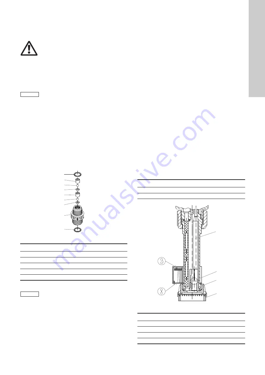
contamination in the suction and discharge valves.
9.1.1 Dismantling and cleaning the valves
1. Unscrew the suction and discharge valves.
2. Use a pin (
∅
2) to press out the ball cage, ball and O-ring from
below.
3. Replace damaged parts.
When re-assembling, observe the correct position of the parts,
see fig.
Fig. 25
Construction of the valves
9.1.2 Dismantling the diaphragm
For safety reasons, the dosing diaphragm should be replaced
after a maximum of 2000 operating hours.
1. Insert the suction lines of the pumps into a water tank, and run
the system until the dosing heads of the pumps have been
well purged with water.
2. Open venting screws by one rotation until the venting lines are
also purged. Switch off the system.
3. Loosen the four dosing head screws.
4. Remove the dosing head, and unscrew the diaphragm by
rotating to the left.
Assembly
1. Insert the intermediate ring so that the relief hole points
downwards.
2. Screw in the diaphragm.
3. Switch on the pump briefly until the diaphragm is located at
the rear dead point.
4. Carefully fit the dosing head, and uniformly and gently tighten
the screws in a diagonally opposite sequence, so that the
dosing head is not damaged.
5. Vent the pump.
9.2 Maintenance of the suction lines
The suction lines are equipped with foot valves and filter nuts.
The Reed contacts are integrated in the suction line body.
The floats with magnet core are located axially on the valve body
and are sliding.
The foot valve should be dismantled and cleaned occasionally,
at the latest when the suction performance drops.
The function symbol (NO contact) must be present on the top
surface of the two floats.
If this is not the case, disconnect the float and reverse the
polarity.
Fig. 26
Suction line, spare parts
Warning
Before any maintenance work, i.e. when exchanging
parts and gaskets, the entire system has to be rinsed
with water.
Before maintenance work, all chemicals must be
completely removed!
When handling acids or lyes, wear appropriate
protective clothing.
Maintenance and repair work must only be carried
out by authorized specialists.
Note
According to the German accident prevention
regulations GUV 8.15 and VGB 65 § 19, chlorine
dioxide systems must be regularly checked for
safety, at least once a year and prior to every startup,
by a specialist.
This check can be carried out by the after-sales
servicing department during the six-monthly
maintenance.
TM
04
82
17
45
10
Pos.
Description
1
Valve body
2
Ball cage
3
Seat
4
Ball
5
O-ring
Note
When installing the valves, make sure that the flow
direction is correct (arrow).
The O-ring must be inserted correctly into the
provided groove.
OCD-164
Product No.
-30 to -220
95730320
(553-1995)
-350 to -2000
95730321
(553-1996)
TM
04
8
221
4
510
Pos.
Description
1
Float switch, PVC
2
Ball
3
Valve seat, grey PVC
4
Filter nut, PVC grey
Содержание Oxiperm OCD-164
Страница 2: ...2...
Страница 247: ...Fran ais FR 247 4 crou filtre PVC gris...
Страница 420: ...RU 420 1 10 1 10 1 20 TrinkwV 2001 0 4 1 10 2 1 10 3 EN 12671 D 15 7 5 DIN EN 938 9 0 DIN EN 939 HCl NaClO2...
Страница 422: ...RU 422 10 10...
Страница 430: ...RU 430 5 4 2 0 1 1 8 5 4 3 42 9 5 4 4 ClO2 ClO2 ClO2 2 3 3 TM04 8200 4510 11 1D O2 O TM04 8201 4510 1D O2 O...
Страница 431: ...RU 431 10 5 5 2 1 5 5 6 5 6 1 5 6 1 TM04 8202 4510 50 60 6 20 11 1D O2 O...
Страница 432: ...RU 432 5 6 2 1 2 3 20 20 4 11 4 5 4 4 5 4 6 5 6 5 6 TM04 8203 4510 1 20 2 3 4 5 6...
Страница 455: ...RU 455 34 HCl 35 HCl 36 NaClO2 37 NaClO2 38 H2O 39 H2O 40 ClO2 41 HCl 42 NaClO2 43 H2O 44 45 46 47...
Страница 526: ...526...


