English (GB)
5
3.3 Storage
To prevent water, dust, etc. from entering the pump, all openings
must be covered until pipes are connected. Apply a suitable
antirust agent on all machined, non-coated surfaces.
The antirust agent must meet these requirements:
• It must not attack rubber parts.
• It must be easy to remove.
• It must be applied according to the instructions of the
manufacturer.
If the pump must be stored for more than six months before start-
up, it must be protected against corrosion and damage:
1. Remove the stuffing box packing.
2. Spray the interior part of the pump case and the stuffing box
with a water-soluble type of antirust agent.
3. If the pump has not been connected to the pipework, cover
the pump suction and discharge flanges with full natural
rubber gasket material, and blank off these openings with
metal blanking flanges. Use at least four bolts for fastening.
4. Cover the opening of the stuffing box with a non-hygroscopic
tape. The stuffing box gland may be left on the pump shaft,
but must be wired or otherwise securely fastened in position.
5. Coat all exposed painted surfaces with an antirust agent that
can be readily removed with a petroleum distillate product.
6. Make sure that all exposed painted surfaces are dry, clean
and free of grease and other contaminates.
7. Cover the pump with a weather-resistant cover of waterproof
paper or plastic material to protect it against dirt and dust.
8. Inspect the pump at regular intervals during storage.
9. Rotate the shaft by hand every four to six weeks to prevent
pitting of the bearings.
4. Product description
4.1 Fire pump set
The fire pump set consists of a pump, an electric motor and a
controller. Pump and motor are connected via a flexible coupling.
All components are adapted to each other and mounted on a
common base frame ready for installation. The base frame is
made of steel channel. The controller can also placed separately.
The fire pump set comes ready for operation.
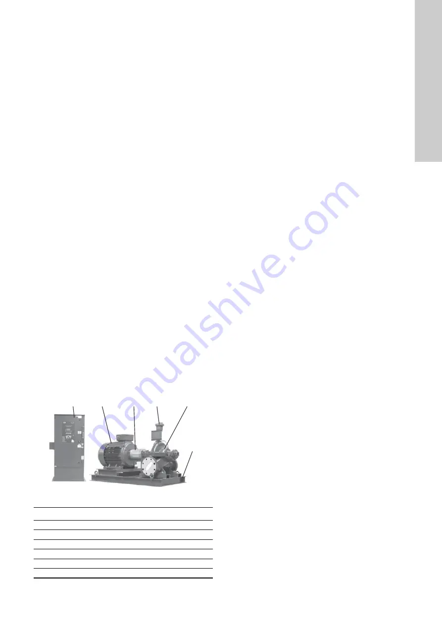
As an example, the most important components of the fire pump
set are shown in fig. 2. It shows an HSEF fire pump set with a
Grundfos horizontal split case pump and an electric motor, type
MMG. Pump and motor are connected by a flexible coupling.
The controller is installed separately.
Fig. 2
Example of fire pump set
4.2 Pump
The fire pump set comes with a Grundfos HSEF horizontal split
case pump or a Grundfos DNF end-suction pump. The pumps are
FM-approved and UL-listed.
The impeller diameter of both pumps can be reduced to
customise the pump performance to a certain duty point.
The actual impeller diameter may therefore deviate from the
standard diameters stated in catalogues, data sheets etc.
The actual impeller diameter is stated on the pump nameplate.
4.2.1 Split case pump
The Grundfos HSEF horizontal split case pump is a non-self-
priming, single-stage pump. It has inline axial suction and
discharge ports with PN 10 or PN 16 ANSI flanges. An adapter
flange from ANSI to DIN is available and must be ordered
separately. The pumps are equipped with a stuffing box, type
SNEA or SNFA (see section
6.1.3 Type key for stuffing box
), and
with an automatic air release valve making venting unnecessary.
4.2.2 End-suction pump
The pumps are non-self-priming, single-stage Grundfos DNF
standard pumps with spiral housing. The pumps have an axial
suction port and a radial discharge port with PN 10 or PN 16 DIN
flanges.
The DNF pump is equipped with a stuffing box, type SNEA or
SNFA. See section
6.1.3 Type key for stuffing box
4.3 Motor
The pumps are driven by a 2- or 4-pole Grundfos MMG-E motor
(15-315 kW) or a Siemens motor (355 kW). All motors are
produced according to IEC 60034. The rated motor power is
adapted to the power requirement of the pump. The combinations
of motors and pumps are shown in section
.
4.4 Controller
4.4.1 General description
The fire pump set is controlled via a Tornatech controller
especially sized for electric motors driving fire pumps.
The controller starts the pump automatically and monitors the
motor. It is FM-approved.
As soon as the sprinklers are activated due to an alarm and water
is consumed, the pressure in the discharge pipe will be reduced.
If the pressure becomes lower than the cut-in pressure set on the
control panel, the pump will start automatically.
Normally, the pump is stopped manually via the controller.
But automatic stop is also possible if all starting causes have
returned to normal.
For test run and set-up, manual operation is possible.
The individual controller models differ mainly by starting method
and power range.
Starting method, model GPA
This model is used where the electricity works or the capacity of
the power source permits direct-on-line starting.
Full voltage is applied to the motor as soon as the controller
receives a start command.
Starting method, model GPY
When the controller receives a start command, the motor is
connected in star. After a time delay, it changes over to delta
connection with full voltage to the motor windings. This controller
is of the open transition type. The motor is disconnected from the
mains during the transition from start (star) to run (delta) mode.
TM
04 51
64 270
9
Pos.
Component
1
Base frame
2
Controller
3
Pump
4
Automatic air release valve
5
Motor
6
Coupling with coupling guard
2
5
6
4
3
1
Содержание Fire DNF
Страница 1: ...Fire DNF Fire HSEF electric Installation and operating instructions GRUNDFOS INSTRUCTIONS...
Страница 34: ...34...


