background image

GRT Avionics, Inc. 


May 2019 


Sport SX Install. Manual 

13 

Rev. A 

SECTION 3: PHYSICAL INSTALLATION 


3-1: Display Unit Installation 

 
Mount  the  display  unit(s)  in  the  desired  location  in  the  instrument  panel.  The  main 
consideration in  choosing a location is the ability to view the display unit and reach its 
controls.  Since  the  screen  is  fully  sunlight-readable,  no  consideration  for  shielding  the 
display unit from sunlight is required. Be mindful of the space behind the instrument panel 
as well; some aircraft with tip-up canopies, for example, have canopy supports that may 
interfere with the back of the EFIS when the canopy is closed. See the 

Appendix 

sections 

A-

1: 6.5” Sport SX Mounting Template

A-

2: 8.4” Sport SX Mounting Template

A-3: 

Sport HS Mounting Template

 and 

A-4: Sport WS Mounting Template

 for display unit 

dimensions and clearance requirements for the rear of the unit. 
 

1.  For panel-mount  style display units,  the use of nut  plates behind the instrument 

panel greatly simplify the task of installing and removing the 4 screws used to retain 
the  display  unit  in  the  panel.  #6  socket  cap  stainless  steel  screws  are 
recommended. 


2.  For radio rack style display units, the #6 screws on the side of the unit (2 per side) 

should be used to attach the display unit to the radio rack. 


3-2: Remote Digital Magnetometer Installation 

 
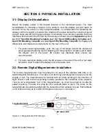
The  remote  magnetometer  must  be  placed  in  an  area  of  the  airplane  with  little  or  no 
electromagnetic interference. The cable is 20 feet long and designed to reach out to the 
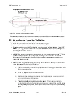
wingtip  or  tail.  The  magnetometer  is  marked  with  an  arrow  pointing  in  the  direction  of 
flight. Mount it with the arrow pointing forward, parallel to the  centerline of the airplane. 
There is not a designated “top” of the magnetometer, so it can be turned on its side for 
easier mounting. The side of a wing tip rib is a simple place to put it. The arrow on the 
magnetometer should be parallel with the centerline of the airplane for yaw. Pitch attitude 
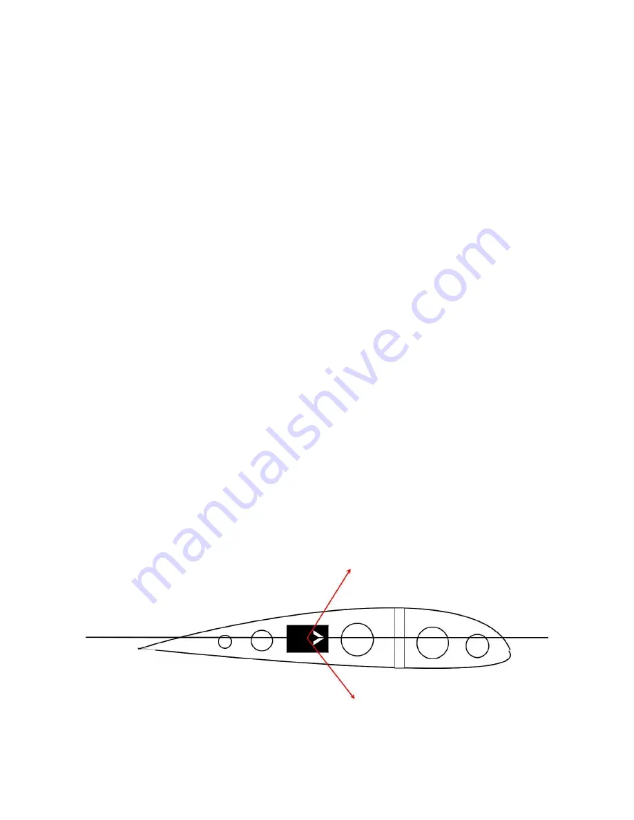
is not critical as long as it is within 60 degrees nose up or nose down. 


  60° up limit 


Longitudinal Axis 


60° down limit 


Figure 3-1: Magnetometer Pitch Range 


Содержание Sport SX

Страница 1: ...Sport SX Installation Manual Including Legacy Sport HS WS Installation Revision A May 2019 GRT Avionics Inc 3133 Madison Avenue SE Wyoming MI 49548 616 245 7700 support grtavionics com grtavionics com...

Страница 2: ...made to ensure that the information in this manual is accurate and complete Visit the GRT website www grtavionics com for the latest manuals software updates and supplemental information concerning th...

Страница 3: ...nics Inc May 2019 Sport SX Install Manual II Rev A RECORD OF REVISIONS Revision Date Sport SW Revision Description A May 2019 SX 15 00 and prior Re issue as a standalone manual for Sport SX Sport HS S...

Страница 4: ...nics Display Units the Inter Display Unit Link 7 2 2 2 Autopilots 8 2 2 3 Autopilot Using GRT Avionics Servos 8 2 2 4 Trio Avionics and TruTrack Flight Systems External Autopilots 8 2 2 5 ADS B Receiv...

Страница 5: ...2 Basic Configuration Settings 21 5 3 Configuring the Serial Ports 21 5 4 Required Setup for the Internal GPS 22 5 5 Internal GPS Settings 22 5 6 AHRS Air Data Computer Test 22 5 7 Setting AHRS Orient...

Страница 6: ...d Analog Legacy 41 A 11 Sport SX200A Suggested Connector A Pinout Diagram Dual Screen System 42 A 12 Legacy Model SX200 Suggested Connector A Pinout Diagram Dual Screen System 43 A 13 Sport SX100 Sugg...

Страница 7: ...documentation NOTE This manual refers to the EFIS display unit and screen although it may seem like these are all interchangeable terms it is important to note that they all refer to different aspect...

Страница 8: ...f another EFIS display unit except for unique data that may be coming from other display units This allows multiple screens to provide redundancy Multiple screens are normally linked together via a se...

Страница 9: ...enhances the usefulness of the engine data by adding such features as an EGT time history percent power and engine efficiency specific fuel consumption The EIS may include its own digital display or m...

Страница 10: ...t display of weather and traffic Displays Traffic Information Service TIS traffic when used with Mode S transponder Interfaces with Garmin SL30 40 to display VOR ILS GS and tune preset radio frequenci...

Страница 11: ...25 725 GPS Comm MFD 635 and GPS Nav Comm MFD 650 750 Single or Dual Interface with Garmin SL30 SL40 XM Satellite Weather Guardian Avionics CO Guardian Series CO Detector TIS Traffic Datalink GTX 330 Z...

Страница 12: ...can occur if the battery becomes disconnected loss of charging etc Electrical connections to the EFIS display unit are made through the D sub connectors affixed to it and its accompanying wiring harn...

Страница 13: ...at any serial port can be used with any device regardless of the baud rate the connection may require The Legacy Sport WS and HS models have a single high speed port serial port 4 which is typically u...

Страница 14: ...r switch for the servos and an engage disengage button A single serial port is used to control both the roll and pitch servos When using multiple GRT EFIS display units any display unit can function a...

Страница 15: ...accuracy and integrity data that is used by the Sport SX The integrity validation performed by this GPS is similar to that performed by IFR certified GPS navigators 2 2 7 Remote Transponders The Sport...

Страница 16: ...e SL30 navigation data to be displayed in the event that one of the display units fails One serial data output from the SL30 may be connected to multiple display units Only one serial data output TO t...

Страница 17: ...structions found in the Sport Setup Guide 2 5 Audio Output The Sport SX feature an audio output it provides a method of alerting the pilot when limits are exceeded altitude call outs on approach traff...

Страница 18: ...ckolls is a great place to start It covers everything from the very basics of electricity to the proper design and installation of sophisticated IFR capable systems EAA columnist Tony Bingelis s books...

Страница 19: ...nstrument panel greatly simplify the task of installing and removing the 4 screws used to retain the display unit in the panel 6 socket cap stainless steel screws are recommended 2 For radio rack styl...

Страница 20: ...ion or landing light wires and more than 18 inches from ferrous metal such as the steel mass balance tube that is typically used in the leading edge of ailerons Use non ferrous hardware or even double...

Страница 21: ...it is oriented correctly Refer to the Magnetometer Installation Notes section of Appendix A Mounting Wiring and Interface Diagrams for additional installation instructions 3 4 Cooling Considerations...

Страница 22: ...ed 3 6 Angle of Attack Pressure Port Connection When equipped with the sensed angle of attack AOA option the pitot static block will also include a port for sensing the AOA using a dual port pitot tub...

Страница 23: ...ould be done carefully to avoid breaking it When routing the wiring the following guidelines should be considered Good practices for physical installation of the wiring should be followed such as grom...

Страница 24: ...should be sized to allow at least 1 5 amps per display unit with a maximum rating of 5 amps Voltage drop in the power and ground wires will cause the EFIS voltmeter to read lower than actual by the a...

Страница 25: ...ometer pair is calibrated together at the factory for optimal accuracy and this pairing should be maintained for the best performance 4 5 Specific Equipment Interconnect Details Most equipment shares...

Страница 26: ...rovided on the D sub connector to drive an external warning light This output provides a path to ground when active thus the indicator should be wired with one of its terminals to aircraft power while...

Страница 27: ...lidate a new installation Note that this counter will advance regardless of whether or not the data being transmitted is at the correct baud rate or even matches the serial port s configuration The co...

Страница 28: ...GPS source internal or external can be assigned to GPS1 or GPS2 at any one time 5 5 Internal GPS Settings The internal GPS provides serial data at 9600 baud in the NMEA0183B format The output from th...

Страница 29: ...there are no grayed out data fields 5 Verify the PFD screen shows HDG next to the heading box at the top center of the screen this indicates that it is receiving valid heading data from the magnetome...

Страница 30: ...heading tape on the PFD for calibration because this is a composite reading of several other pieces of information The Magnetic Heading field contains instantaneous data on the magnetic heading only...

Страница 31: ...t no built in test failure will be reported while the wiring is still incorrect This can occur if the magnetometer X Y Z inputs are swapped To check for this point the airplane at various directions l...

Страница 32: ...meter must be calibrated before the first flight of the aircraft Magnetometer calibration is required to achieve accurate magnetic heading readings This calibration corrects for errors induced by magn...

Страница 33: ...in a counter clockwise manner initially towards west The airplane does not need to be rotated in place but simply pulled or taxied in a circle The airplane must be rotated completely through the 380...

Страница 34: ...will be within 30 if the magnetometer was mounted in a good location and was mounted accurately with respect to the AHRS The status of the magnetometer correction data is indicated by the field next t...

Страница 35: ...ill be falsely reported as a cross wind Thus with only a 5 heading error an airplane flying at 100 knots will show a false crosswind of 8 5 knots 5 15 Required Settings Before Flying In addition to th...

Страница 36: ...desired Engine Limits Limits Review all limits if engine data is provided to the EFIS Engine Performance Limits Not required but useful for assuring power is below 75 for learning Fuel Scale Data Lim...

Страница 37: ...included in this Appendix show the function of each D sub connector terminal position and its associated wire color Functions labeled NC have no connection or are terminal positions that should remai...

Страница 38: ...ting Template All dimensions are in inches NOT TO SCALE Panel Cutout 6 24 x 5 19 This allows for clearance on each side Use No 6 screws for mounting NOTE The depth of the display unit is approximately...

Страница 39: ...e panel face allow for an additional 3 5 to 4 behind the display unit for wiring and pitot static connections A 2 8 4 Sport SX Mounting Template Figure A 2 8 4 Sport SX Mounting Template All dimension...

Страница 40: ...GRT Avionics Inc May 2019 Sport SX Install Manual 34 Rev A A 3 Sport HS Mounting Template Figure A 3 Sport HS Mounting Template NOT TO SCALE...

Страница 41: ...GRT Avionics Inc May 2019 Sport SX Install Manual 35 Rev A A 4 Sport WS Mounting Template Figure A 4 Sport WS Mounting Template All dimensions are Inches NOT TO SCALE...

Страница 42: ...nal GPS Module RAIM GPS Module ARINC Module Magnetometer NOTE Drawing shows height of module mounting platform only GPS and ARINC modules are 9 16 taller than mount Allow an extra 3 above ARINC module...

Страница 43: ...GRT Avionics Inc May 2019 Sport SX Install Manual 37 Rev A Figure A 7 Magnetometer Installation A 6 Magnetometer Installation Diagram...

Страница 44: ...nternal GPS NOTE Serial Port 3 is used for the Internal GPS when optionally installed The receiving port and GPS module are located inside the EFIS display unit Pin 32 functions as an output to feed G...

Страница 45: ...th CPU GPU processor upgrade AHRS Maintenance page AHRS software versions less than 50 or 0 50 are legacy type AHRS Recommended serial port usage in italics Pin Function Wire Color 20 Audio SW Ver 11...

Страница 46: ...es to SX with CPU GPU processor upgrade AHRS Maintenance page AHRS software versions less than 50 or 0 50 are legacy type AHRS Recommended serial port usage in italics Pin Function Wire Color 20 Audio...

Страница 47: ...ctor as damage may occur while pulling them through the airframe The magnetometer wires connector attaches to the magnetometer s mating D sub connector A male connector for the Digital Magnetometer an...

Страница 48: ...essor upgrade AHRS Maintenance page AHRS software versions less than 50 or 0 50 are legacy type AHRS Recommended serial port usage in italics Pin Function Wire Color 20 Audio SW Ver 11 and up 21 GPS M...

Страница 49: ...with CPU GPU processor upgrade AHRS Maintenance page AHRS software versions less than 50 or 0 50 are legacy type AHRS Recommended serial port usage in italics Pin Function Wire Color 20 Audio SW Ver...

Страница 50: ...rial Port 4 is the only high speed port in HS and WS Sport EFIS models making it the only port suitable for XM Weather NOTE Applies to SX with CPU GPU processor upgrade in these units All five SX seri...

Страница 51: ...m the AOA port on the pitot tube to the AOA port on the pitot static block The AOA port on the pitot static block is the center port between the Pitot and Static ports for instruments equipped with th...

Страница 52: ...8 4 Sport SX Faceplate 8 7 W x 6 47 H Depth of Display Unit 4 75 Behind Panel Face Approx Panel Opening 8 064 W x 6 33 H Weight 4 2 lbs Sport EFIS Specifications Max Angular Rate SX200 200 s All Axis...

Страница 53: ...port SX Mounting Template 33 A 3 Sport HS Mounting Template A 3 Sport HS Mounting Template 34 A 4 Sport WS Mounting Template A 4 Sport WS Mounting Template 35 A 5 External Module Top View A 5 External...

Страница 54: ...iew A 13 Sport SX100 Suggested Connector A Pinout Diagram Multi Screen System 44 A 10 9 Position Female D sub Connector A 10 Magnetometer Digital and Analog Legacy 41 A 11 9 Position Male D sub Connec...

Отзывы: