


PAGE 1 of 4 LIT-258
ADJUSTING THE HANDPIECE
To position the hose, loosen the locking ring a little. With the locking ring slightly
loose, the handpiece body and knob can be turned independently. Position the
Quick Change holder with the graver “point” down. Rotate the knob until the
hose position is comfortable, then tighten the locking ring.
The length of the handpiece can be extended a little by unscrewing the knob
and body even more. NOTE: When the handpiece length is extended, a loss of
power may occur, depending on the type of work being done.
ATTACHING A NEW HOSE
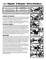
Loosen the locking ring (FIG. 1). Remove the knob from the handpiece. Remove
the hose by cutting it off close to the knob. With a small punch, push the hose /
brass fitting back into the knob body. Remove the brass fitting (#044-031) from
the hose. Feed the new air hose through the hole in the knob (FIG. 2). Insert the
brass fitting into the end of the new hose, making sure it is fully seated.
If needed, lubricate the fitting first to help it slip into the hose easier. Then apply a
small amount of water or oil around the outside end of the hose next to the brass
fitting and pull the hose back (FIG. 3) into the knob until you see the tip of the
brass fitting protrude through the side of the knob. This must be an air tight fit, so
a bit of force may be needed (a few pounds of pressure, at least).
MAINTENANCE
Keep the Magnum handpiece clean on the inside. Problems will occur if oil or
moisture gets into the handpiece, especially on the piston. If you notice a loss
of power or erratic performance, first check if the receiver (chuck) is tight in the
handpiece body. Using a crescent wrench or pliers with a graver inserted in
the QC Holder, gently tighten receiver clockwise (FIG. 4) If erratic performance
continues, then disassemble and clean the handpiece. To disassemble the
handpiece, use the crescent wrench or pliers to grip the graver (FIG. 4) and
turn it counterclockwise to loosen the chuck retainer.
After loosening, turn the chuck retainer out with your finger tips (FIG. 5). As the
chuck is pulled out, there will be a spring and piston that follows. Loosen the
locking ring and remove it (FIG. 6). Grip the knob and turn the handpiece body
counterclockwise until it is out of the knob body (FIG. 7).
Now, with the handpiece disassembled, clean the parts with a non-residue
solvent like denatured alcohol. Make sure the holes in the handpiece body
are clear from dirt and debris. DO NOT get moisture down the air hose. If this
happens you will need to clear and dry it before reassembly.
Before reassembly, make sure every thing is completely dry. DO NOT OIL
INSIDE THE HANDPIECE. NO lubricant is required. Lubricant will actually
decrease performance!
Magnum
®
& Magnum
®
Airtact Handpiece
INSTRUCTIONS • #004-940, #004-940-OVAL , #004-941, #004-940-ATSS & #004-957SS
Standard Spring
Normal Operating Range
18-22 psi (1.2-1.5 bar) /
1400 - 3400 spm
Recommended Initial Setting
19 psi (1.3 bar) / 2700 spm
PSI: Pounds per Square Inch • Bar: Unit of Measurement • SPM: Strokes Per Minute
LOCKING RING
Loosen first
FIG. 1
Lubricate end
slightly with
water or a small
amount of oil.
LOOSEN
TURN COUNTERCLOCKWISE
TIGHTEN
TURN CLOCKWISE
LOCKING
RING
FIG. 2
FIG. 3
FIG. 4
FIG. 5
FIG. 6
FIG. 7


