background image

12

11

5.1 Safety instructions

4


Unpacking and inspection

Installation 5


The  inverter  is  thoroughly  tested  and  inspected  strictly  before  delivery.  Our  inverters 

leave  our  factory  in  proper  electrical  and  mechanical  condition.  Special  packaging 

ensures safe and careful transportation. However, transport damage may still occur. The 

shipping  company  is  responsible  in  such  cases.  Thoroughly  inspect  the  inverter  upon 

delivery.  Immediately  notify  the  responsible  shipping  company  if  you  discover  any 

damage to the packaging which indicates that the inverter may have been damaged or if 

you discover any visible damage to the inverter. We will be glad to assist you, if required. 

When transporting the inverter, the original or equivalent packaging should be used, and 

the maximum layers for original carton is four, as this ensures safe transport.

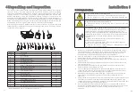
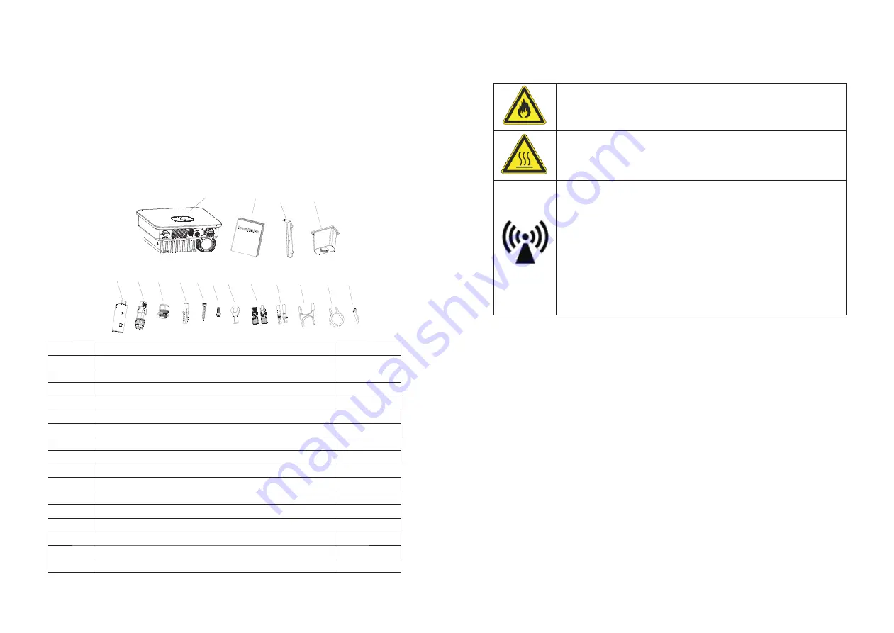
After opening the package, please check the contents of the box. It should contain the 

following, Please check all of the accessories carefully in the carton. If anything missing, 

contact your dealer at once. 

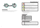
Danger to life due to fire or explosion

Ø

Despite careful construction, electrical devices can cause fires.

Ø

Do  not  install  the  inverter  on  easily  flammable  materials  and 

where flammable materials are stored.

Risk of burns due to hot enclosure parts

Ø

Mount  the  inverter  in  such  a  way  that  it  cannot  be  touched 

inadvertently.

Possible damage to health as a result of the effects of radiation!

Ø

In special cases, there may still be interference for the specified 

application area despite maintaining standardized emission limit 

values (e.g. when sensitive equipment is located at the setup location 

or when the setup location is near radio or television receivers).In this 

case, the operator is obliged to take proper action to rectify the 

situation.

Ø

Never install the inverter near the sensitive equipment

e.g. 

Radios, telephone, television, etc

Ø

Do not stay closer than 20 cm to the inverter for any length of 

time unless it is absolutely necessary.

Ø

Growatt  assumes  no  responsibility  for  compliance  to  EMC 

regulations for the complete system

Ø

Ø

Ø

Ø

Ø

Ø

Ø

Ø

Ø

All electrical installations shall be done in accordance with the local and national 

electrical codes. Do not remove the casing. Inverter contains no user serviceable 
parts. Refer servicing to qualified service personnel. all wiring and electrical 

installation should be conducted by a qualified service personnel .

Carefully remove the unit from its packaging and inspect for external damage. If you 

find any imperfections, please contact your local dealer.

Be sure that the inverters connect to the ground in order to protect property and 

personal safety.
The inverter must only be operated with PV generator. Do not connect any other 

source of energy to it.
Both AC and DC voltage sources are terminated inside the PV Inverter. Please 

disconnect these circuits before servicing.

This unit is designed to feed power to the public power grid (utility) only. Do not 

connect this unit to an AC source or generator. Connecting Inverter to external 

devices could result in serious damage to your equipment.

When a photovoltaic panel is exposed to light, it generates a DC voltage. When 

connected to this equipment, a photovoltaic panel will charge the DC link 

capacitors. 

Energy stored in this equipment's DC link capacitors presents a risk of electric shock. 

Even after the unit is disconnected from the grid and photovoltaic panels, high 

voltages may still exist inside the PV-Inverter. Do not remove the casing until at least  

5  minutes after disconnecting all power sources.
Although designed to meet all safety requirements, some parts and surfaces of 

Inverter are still hot during operation. To reduce the risk of injury, do not touch the 

heat sink at the back of the PV-Inverter or nearby surfaces while Inverter is 

operating. 

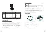
Quantity

A

B
C
D
E
F
G
H

I

J

K
L

Inverter
Quick Guide
Mounting bracket

AC waterproof cover

Monitor(Optional)

Waterproof connector

Self-tapping screw
Security screw

AC OT terminal

PV Male &Female cable coupler
PV Pin&Socket contacts

1
1
1
1
1
1
1

3

3

3

1

3/4

Object

Description

Plastic expansion tube

4PIN or 16PIN COM port signal connector

A

B

C

D

E

F

G

H

I

J

L

M

N

O

K

P

M
N
O
P

COM port removal tool
PV terminal removal tool
AC terminal block insulation partition

3/4

1
1
2

*

*

*

     MIN7000-8000TL-X \X(E)  3  MIN9000-10000TL-X  4

Содержание MIN 10000TL-X

Страница 1: ...gy Co Ltd 4 13 F Building A Sino German Europe Industrial Park Hangcheng Ave Bao an District Shenzhen China GR UM A 0 229 1 86 0755 2747 1942 86 0755 2747 1942 www ginverter com www ginverter com T E...

Страница 2: ...on of skilled person 2 3 Safety instruction 2 4 Assembly Warnings 2 5 Electrical Connection Warnings 2 6 Operation Warnings 1 1 Validity 1 2 Target Group 1 3 Additional information 1 4 Symbols in this...

Страница 3: ...ication 14 2 DC connector and Isolator info 14 3 Torque 14 4 Accessories 6 Electrical connection 13 Decommissioning 7 Commissioning 14 Technical Data 7 1 Start the inverter 7 2 General setting 7 3 Adv...

Страница 4: ...he Growatt equipment or personal injury This manual describes the assembly installation commissioning and maintenance of the following Growatt Inverter model MIN 7000 TL X X E MIN 8000 TL X X E MIN 90...

Страница 5: ...les Nevertheless improper use may cause lethal hazards for the operator or third parties or may result in damage to the units and other property Principle of a PV plant with this MIN TL X single phase...

Страница 6: ...al voltage in the inverter The inverter takes 20 minutes to ischarge The components in the inverter are live Touching live components can result in serious injury or death DANGER WARNING Ensure all co...

Страница 7: ...nverter status LED color LED status Standby Green 0 5s on and 2s off Normal Green Solid Fault Red Solid Warning Green 0 5s on 0 5s off 0 5s on 2s off Programming Yellow 1s on and 1s off A C B D E F H...

Страница 8: ...34 8A 0 8leading 0 8lagging 0 8leading 0 8lagging IP 66 IP 66 with derating above 45 C 113 F 25 60 13 140 F 25 60 13 140 F with derating above 45 C 113 F Model Height H Width W Depth D Weight MIN 00...

Страница 9: ...he complete system All electrical installations shall be done in accordance with the local and national electrical codes Do not remove the casing Inverter contains no user serviceable parts Refer serv...

Страница 10: ...ut of the children s reach Don t put any things on the inverter Do not cover the inverter Do not install the inverter near television antenna or any other antennas and antenna cables Inverter requires...

Страница 11: ...leave 2 to 4mm exposed Falling equipment can cause serious or even fatal injury never mount the inverter on the bracket unless you are sure that the mounting frame is really firmly mounted on the wal...

Страница 12: ...safely disconnected under load NOTE The inverter has the function of detecting residual current and protecting the inverter against residual current you must choose a Type A RCD breaker with the rati...

Страница 13: ...ndard 62109 you must install the protective conductor on the AC terminal with a conductor cross section of at least 10 mm Cu Or Install a second protective conductor on the earth terminal with the sam...

Страница 14: ...PV plant The Max open circuit voltage which can occur at solar panels temperature of 15 must not exceed the Max input voltage of the inverter WARNING WARNING Improper operation during the wiring proce...

Страница 15: ...ed sleeve to connection terminal until both are locked tightly on Uninstall signal connector Step 1 Press the fasteners and pull it out from the inverter NC No Definition 1 2 3 4 12V COM RS 485A1 RS 4...

Страница 16: ...40mA The CT Model is ESC16 32 ECHUN CTF16 2K5 32 Shenke The primary aperture is 10mm output cable length is 5m The arrow on the CT must pointing towards the inverter The detailed information about the...

Страница 17: ...nvalid Information CAUTION 6 8 1 16Pin socket pin assignment COM Socket Pin No Assignment for inverters capable of discharging both charging and 9 10 11 12 13 14 DRM 5 DRM 6 DRM 7 DRM 8 RefGen Com DRM...

Страница 18: ...es that newly installed PV systems attached to a building must be fitted with a means of detecting and disconnecting serial electric arcs AFCI on the PV side 6 9 2 Danger information Danger of fire fr...

Страница 19: ...the inverter 7 1 1 Touch control 7 1 2 Country Area and Region setting Touch Single touch Double touch Three touch Hold 5s Description Switch display or Number 1 Enter Previous menu Confirm country se...

Страница 20: ...tection settings 7 1 3 Enabling Disabling Power Quality Response Modes PQRM Information PQRM setting When the Region setting is completed the inverter will operate under default mode different from re...

Страница 21: ...er 1 Double touch to confirm you setting Hold 5s recover defaut value Set Date 2018 12 14 Set Time 12 30 30 Set Date 2018 12 14 Set Date 2018 12 14 Set Time 12 30 30 Set Time 12 30 30 Set OK Set OK Se...

Страница 22: ...to switch display or make the number 1 Double touch to confirm you setting Control type SW stands for enabling software limit control function HW stands for enabling hardware limit control function B...

Страница 23: ...cause all configured parameters except the current date time and model parameters will be restored to their factory defaults Reset factory NO YES Set OK Set parameter General Advanced Password 7 3 4 A...

Страница 24: ...inverter will start automatically when the input voltage is higher than 60 V 8 1 Start Up the inverter 8 2 Shut down the Inverter 9 1 Checking Heat Dissipation 9 2 Cleaning the Inverter Turn off the...

Страница 25: ...ation of your inverter please read through the following information to correct the problem 11 1 Error Messages displayed on OLED An error message will be displayed on the OLED screen when a fault occ...

Страница 26: ...till exist contact Growatt Auto Test Failed Error 407 Auto test didn t pass PV Voltage High Error 202 The DC input voltage is exceeding the maximum tolerable value 1 Disconnect the DC switch immediate...

Страница 27: ...still exist Contact Growatt Error 422 The data sampled by the DSP and redundant M3 is not the same 12 Manufacturer Warranty Please refer to the warranty card 13 Decommissioning 13 1 Dismantling the I...

Страница 28: ...nverter backfeed current to PV array 0A Power factor nominal power 0 99 Adjustable power factor 0 8leading 0 8lagging THDi 3 AC grid connection type Single phase Overvoltage category PV II AC III Othe...

Страница 29: ...feed current to PV array 0A Power factor nominal power 0 99 Adjustable power factor 0 8leading 0 8lagging THDi 3 AC grid connection type Single phase Overvoltage category PV II AC III Others I Efficie...

Страница 30: ...able you will find the optional accessories for your product If required you can order these from GROWATT NEW ENERGY CO LTD or your dealer Shipped to a Growatt service centre for repair or repaired on...

Страница 31: ...r type Serial number of the inverter Event number or display message of the inverter Type and number of PV modules connected Optional equipment SHENZHEN GROWATT NEW ENERGY CO LTD 4 13 F Building A Sin...

Отзывы: