background image

41

42

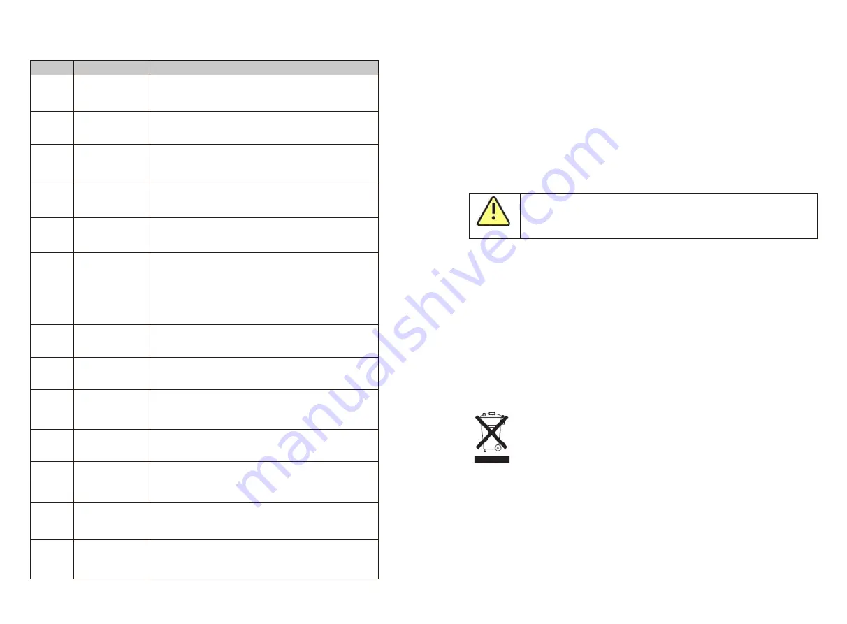
Error code

Description

Suggest

Error 413 Drive exception

1.Restart the machine;

2.If  the  fault  information  still  exists,contact  the 

manufacturer.

Error 414 Memory exception

1.Restart the machine;

2.If  the  fault  information  still  exists,contact  the 

manufacturer.

Error 415

Abnormal

a u x i l i a r y  p o w e r 

supply

1.Restart the machine;

2.If  the  fault  information  still  exists,contact  the 

manufacturer.

Error 416 Overcurrent

protection

1.Restart the machine;
2.If  the  fault  information  still  exists,contact  the 
manufacturer.

Error 417

The  grid  voltage 
sampling is
inconsistent

 1.Restart the machine;

2.If  the  fault  information  still  exists,contact  the 

manufacturer.

Error 418

The firmware

version of the

control  board  and 

the

c o m m u n i c a t i o n  

board do not

match

1.Restart the machine;
2.If  the  fault  information  still  exists,contact  the 
manufacturer.

Error 419

Inconsistent
leakage current
sampling

1.Restart the machine;
2.If  the  fault  information  still  exists,contact  the 
manufacturer.

Error 420

Leakage  current 
module is
abnormal

1. Restart the machine;
2.If  the  fault  information  still  exists,contact  the 
manufacturer.

Error 421 CPLD abnormal

1.Restart the machine;
2.If  the  fault  information  still  exists,contact  the 
manufacturer.

Error 422

Redundant
sampling is
inconsistent

1.Restart the machine;

2.If  the  fault  information  still  exists,contact  the 

manufacturer.

Error 423

Abnormal  battery 

reverse

connection

protection tube

1.Restart the machine;

2.If  the  fault  information  still  exists,ontact  the 

manufacturer.

Error 424

Battery voltage

sampling is

inconsistent

1.Restart the machine;

2.If  the  fault  information  still  exists,ontact  the 

manufacturer.

Error 425 AFCI self-check

error

1.Restart the machine;

2.If  the  fault  information  still  exists,ontact  the 
manufacturer.


Manufacturer warranty


14

Please refer to the warranty card.


Decommissioning


15

15.1 Dismantling the Inverter

15.2 Packing the Inverter

 1. Disconnect the inverter as described in section8.

 2. Remove all connection cables from the inverter.

3. Screw off all projecting cable glands.
4. Lift the inverter off the bracket and unscrew the bracket screws.

CAUTION

Danger of burn injuries due to hot enclosure parts!

Wait 20 minutes before disassembling until the housing has cooled down.

If possible, always pack the inverter in its original carton and secure it with tension belts. 

If it is no longer available, you can also use an equivalent carton. The box must be 

capable of being closed completely and made to support both the weight and the size of 

the inverter.

15.3 Storing the Inverter

Store the inverter in a dry place where ambient temperatures are always between -25°C 
and +60°C.

15.4 Disposing of the Inverter

Do  not  dispose  of  faulty  inverters  or  accessories  together  with  household 
waste. Please accordance with the disposal regulations for electronic waste 
which apply at the installation site at that time. Ensure that the old unit and, 
where applicable, any accessories are disposed of in a proper manner

Содержание MID 17KTL3-X1

Страница 1: ...henzhen P R China No 28 Guangming Road Shiyan Street Bao an District Shenzhen P R China 86 755 2747 1942 www ginverter com www ginverter com T E W service ginverter com service ginverter com 86 755 27...

Страница 2: ...cation of skilled person 2 3 Safety instruction 4 Unpacking inspection 5 Installation 5 1 Basic installation requirements 5 2 Mounting wall mount 5 3 Installing the inverter 6 1 Security 6 2 AC side w...

Страница 3: ...nty 15 Decommissioning 17 Specification 16 EU declaration of conformity 18 EU declaration of conformity 9 1 Boot display 9 2 OLED display wake up 9 3 Function setting 12 1 Start the inverter 12 2 Shut...

Страница 4: ...ted to the Growatt device or cause personal injury 1 3 2 Markings on this product CAUTION CAUTION indicates a hazardous situation which if not avoided could result in minor or moderate injury NOTICE i...

Страница 5: ...nverter and other communication products to communicate with each other The wireless communication device is not standard Require to order extral if you need it Safety 2 2 1 Product description and fe...

Страница 6: ...e incorrect installation and operation may lead to serious safety and shock hazards and or equipment damage In order to minimize the possibility of shock hazards due to dangerous voltages cover the en...

Страница 7: ...ugh charge to create a shock hazard In order to minimize the occurrence of this situation observe all corresponding safety symbols and marks in this manual Under special circumstances the inverter may...

Страница 8: ...k whether the outer package is damaged After unpacking please check whether the appearance of the inverter is damaged or lack of accessories If there is damage or missing parts please contact the deal...

Страница 9: ...y of the installation environment should be between 0 and 90 The ambient temperature around the inverter should be between 25 C 60 C The inverter can be mounted on a plane that is tilted vertically or...

Страница 10: ...wall for power or other piping before opening the hole in the wall Danger Secure the wall mount as shown do not let the screws flush with the wall instead expose 2 to 4 mm 5 3 Installing the inverter...

Страница 11: ...gle core wire at the output terminal of the inverter It is forbidden to use aluminum wires as output cables Please ensure that the output cable is well connected before turning on the inverter Ignorin...

Страница 12: ...witch Measure the voltage and frequency of the public grid voltage AC 230V frequency 50Hz The recommended specifications of the AC output switch are as follows Inverter model Switch specification MID...

Страница 13: ...utput terminal before turning it on otherwise the inverter will be damaged If a stable non zero DC voltage is measured between the positive pole of the photovoltaic string and the ground it means that...

Страница 14: ...ive connector Negative metal terminal 4 6mm 4 6mm Fig 6 7 Fig 6 8 Fig 6 9 1 2 3 4 B just for Vietnam models B just for Vietnam models A A Fig 6 10 Fig 6 11 Fig 6 12 Fig 6 13 2 Push the threaded sleeve...

Страница 15: ...In this case the company does not carry out warranty and assumes any responsibility Photovoltaic panel Inverter Distribution Cabinet SPD Power grid Lightning protection device Grounding bar 1 2 3 4 To...

Страница 16: ...the disconnection device Do not generate power Do not generate at more than 50 of rated power Do not generate at more than 75 of rated power and reduce the reactive power as far as possible Increase...

Страница 17: ...n permanent shutdown The inverter has large electrical potential differences between its conductors Arc flashes can occur through air when high voltage current flows Do not work on the product during...

Страница 18: ...uency return to normal the inverter will automatically connect to the grid 8 2 Failure mode The inverter controls the chip monitors and adjusts the state of the system in real time When the inverter m...

Страница 19: ...er than the domestic legal requirements the inverter cannot be connected to the grid After obtaining the permission of the local power operator the user can choose other voltage levels according to th...

Страница 20: ...0 2 USB A The inverter side The inverter side The inverter side The inverter side Unistall up Install USB A port is mainly used to connect monitoring module or firmware update We can connect the exter...

Страница 21: ...ct terminal abnormal 1 Check the string terminal wiring after shutdown 2 If the fault message still exists contact the manufacturer Warning 202 DC lightning protection device alarm 1 Check the DC ligh...

Страница 22: ...manufacturer Warning 305 Reverse connection of current transformer 1 Check whether the current transformer is connected reversely 2 If the fault message still exists contact the manufacturer Warning 3...

Страница 23: ...line 2 If the fault information still exists contact the manufacturer Error 308 Pairing timeout 1 The pairing of the machine and the current transformer is overtime re pair 2 If the fault information...

Страница 24: ...ttery reverse connection protection tube 1 Restart the machine 2 If the fault information still exists ontact the manufacturer Error 424 Battery voltage sampling is inconsistent 1 Restart the machine...

Страница 25: ...voltage 1100V Start voltage 250V Nominal voltage 600V MPP voltage range 200 1000V No of MPP trackers 3 No of PV strings per MPP trackers 2 2 2 2 2 2 2 2 2 2 2 2 Max input current per MPP trackers 26A...

Страница 26: ...RS485 YES WIFI GPRS 4G RF LAN OPT Model Specifications MID 30KTL3 X MID 33KTL3 X MID 36KTL3 X MID 40KTL3 X Input data DC Max recommended PV power for module STC 45000W 49500W 54000W 60000W Max DC volt...

Страница 27: ...5 YES WIFI GPRS 4G RF LAN OPT Model Specifications MID 17KTL3 X1 MID 20KTL3 X1 MID 22KTL3 X1 MID 25KTL3 X1 Input data DC Max recommended PV power for module STC 25500W 30000W 33000W 375000W Max DC vol...

Страница 28: ...YES WIFI GPRS 4G RF LAN OPT Model Specifications MID 30KTL3 X MID 33KTL3 X MID 36KTL3 X MID 40KTL3 X Input data DC Max recommended PV power for module STC 45000W 49500W 54000W 60000W Max DC voltage 11...

Страница 29: ...aces Display OLED LED USB RS485 YES WIFI GPRS 4G RF LAN OPT 17 2 Torque Shell cover screw 12kgf cm AC terminal block 14kgf cm AC waterproof cover fixing screw 4kgf cm Security screws on the wall mount...

Страница 30: ...act the Growatt New Energy Service Hotline We need the following information to provide you with the necessary help Inverter type Inverter serial number Inverter error message code Inverter OLED displ...

Отзывы: