5
Control reverts to normal mode.
Pressing the radio transmitter again following successful
registration (in normal mode) triggers flushing.
Further radio transmitters are registered as described above.
Deleting a radio transmitter
1. Press button (F) (LED flashes once briefly in confirmation)
and hold for 8 seconds.
2. Holding the button continuously for 8 seconds deletes all
registered radio transmitters; LED flashes once briefly in
confirmation.
Control reverts to normal mode.
Setting the flow volume
1. Activate registration mode by pressing the button;
LED flashes once in confirmation.
2. Press and hold the button again in registration mode.
LED flashes rapidly in confirmation.
This flashing signal is interrupted for 1 second
after 5 seconds.
3. Release the button within 2 seconds. Flush duration
adjustment mode is activated.
4. The flow volume is selected by pressing the button
- button pressed for first time (within 2 seconds):
3 flashing signals = flow volume 3 litres
- button pressed for second time (within 2 seconds):
4 flashing signals = flow volume 4 litres
- button pressed for third time (within 2 seconds):
5 flashing signals = flow volume 5 litres
- button pressed for fourth time (within 2 seconds):
6 flashing signals = flow volume 6 litres (factory setting)
- button pressed for fifth time (within 2 seconds):
7 flashing signals = flow volume 9 litres
- button pressed for sixth time (within 2 seconds):
3 flashing signals = flow volume 3 litres
After the group with 7 flashing signals, the routine starts from
the beginning.
5. The flow volume is selected by refraining from pressing the
button within 2 seconds after the desired flow volume is
signalled.
6. One flush is performed at the set volume with the signal
flashing once more.
7. The flow volume can be changed within 20 seconds of
flushing (if necessary) by pressing the button again. The
selected flush setting is stored if the button is not pressed
again within 20 seconds of flushing.
Control reverts to normal mode.
Switching 72-hour flush on and off
(factory setting: switched on)
1. Activate registration mode by pressing the button.
LED flashes once in confirmation.
2. Press and hold the button again in registration mode.
LED flashes rapidly in confirmation.
The signal is interrupted for 1 second after 5 seconds.
3. Keep the button pressed. After 5 seconds, the LED
extinguishes for 2 seconds. The LED then illuminates
continuously.
4. Release the button.
5. Switch the 72-hour flush on or off by pressing the button
again within the following 2 seconds.
- 4 short flashing signals after the button is pressed =
72-hour flush is switched on.
- 2 long flashing signals after the button is pressed =
72-hour flush is switched off.
6. Each press of the button switches between the two states.
7. If the button is not pressed again within 10 seconds, control
reverts to normal mode.
Maintenance
• Shut off water supply
• Switch off voltage supply
• Inspect and clean all components and replace if necessary
See technical product information for cistern for
information on maintaining the cistern parts.
Replacing the transformer
, see fold-out page III, Fig. [29]
Replacing the servo motor
1. Disassemble plate, see fold-out page III, Fig. [27].
2. Disconnect plug-in connectors, see Fig. [30].
3. Disassemble servo motor, see Fig. [31a] or [31b].
4. Calibrate new servo motor, see
Calibrating the servo
motor
.
5. Install new servo motor, see
Installing the servo motor
.
6. Install wall plate, see
Installing the plate
.
Replacing the electronics
1. Disassemble plate, see fold-out page III, Fig. [27].
2. Disconnect plug-in connectors, see Fig. [30].
3. Disassemble servo motor, see Fig. [31a] or [31b].
4. Replace electronic module, see Fig. [32].
5. Calibrate servo motor, see
Calibrating the servo motor
.
6. Install servo motor, see
Installing the servo motor
.
7. Register radio transmitter, see
Registering a radio
transmitter
.
8. Install wall plate, see
Installing the plate
.
Calibrating the servo motor
Caution
: The servo motor must be calibrated outside the
cistern.
1. Connect voltage supply, see fold-out page IV, Fig. [33].
The servo motor must not be connected when
performing this operation.
The LED in the electronics begins to flash.
2. Connect servo motor to electronic module, see Fig. [34].
The LED in the electronics stops flashing and adjustment
automatically starts. The servo motor moves to the
adjustment positions.
Caution
: It must be ensured that the movement is not
disrupted by obstacles.
To prevent falsification of the servo motor adjustment, the lever
must not be removed.
Calibration has been completed when lever is at approx. 90°
and the LED in the electronics does not flash, otherwise see
section:
Fault/cause/remedy
.
3. Disconnect plug-in connectors, see Fig. [35].
Replacement parts
, see fold-out page I (* = special
accessories).
Care
For directions on the care of this fitting, please refer to the
accompanying Care Instructions.
Содержание TECTRON 38 759
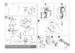
Страница 3: ...II A 5 6 O 2 1 8 7 9 R R1 10 B 11 12 1 2 13 14 1 180 2 15a 16 17 1 2 3 18 21 15b 19 20 ...
Страница 37: ...34 ...
Страница 38: ...35 ...
Страница 39: ...36 ...
Страница 85: ......
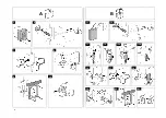
Страница 86: ...III 22a M L 23 26 24 22b 25 30 31a 27 N O 28 230 V AC 29 32 31b ...
Страница 87: ...IV 1 2 2 1 34 35 33 ...


