Principle of operation
10
Dat
e
of i
ss
u
e : J
a
nu
a
ry 2011
Automatic Greasing System
Twin-3
EG1703P03
2.3
Twin pump unit
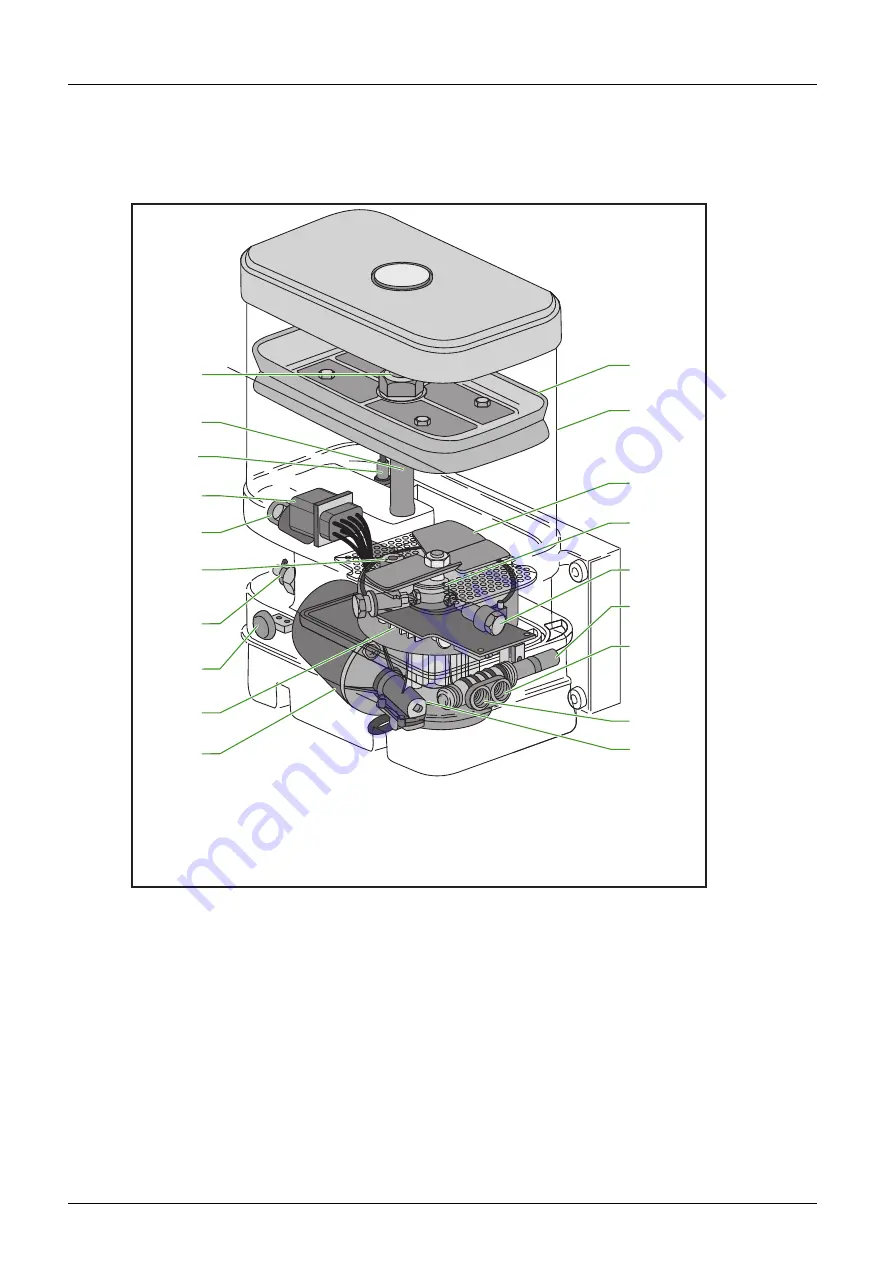
The Twin pump unit consists of various parts. These parts are shown in Figure 2.2.
Figure 2.2
Twin pump unit
The heart of the pump is an electrical-driven piston-pump. This pump consists of three radially-
placed fixed cylinders and pistons (5). The electromotor drives the axle through the mechanical
transmission (9). A cam (4) is fixed on the axle that moves the three pistons to and fro, so the grease
is pumped to the distribution blocks through the primary grease lines. In addition to the cam, the
axle drives the stirring gear (3) located at the bottom of the reservoir and pushes the grease
downwards. A compression channel is located between the pump and the grease channels to the
primary lines. A relief valve (14) and a 5/2-way valve (6) are located in the compression channel.
The relief valve is a protection that leads the grease back to the reservoir when the grease pressure
exceeds 250 bar. The 5/2-way valve determines the primary grease line-A or -B through which
greasing takes place. It has an important task in fulfilling the four phases of the greasing cycle (see
paragraph 2.2).
1
2
3
4
5
6
7
8
9
1
2
11
1
0
1
3
1
4
1
5
16
1
7
18
1
9
1. Follower plate
2. Grease reservoir
3. Stirring gear
4. Cam
5. Cylinder and pistons (3x)
6. 5/2-way valve
7. Primary grease line-A outlet
8. Primary grease line-B outlet
9. Mechanical transmission
10. Electro-motor
11. Control unit
12. Test push-button
13. Filler coupling with grease filter
14. Relief valve
15. Bleeding and grease overflow out-
let
16. Electric connector
17. Minimum level switch
18. Guide rod follower plate
19. Bleeding and grease overflow
channel, connected to the
bleeding and grease overflow
outlet (no. 15)
Содержание EG1703P03
Страница 4: ...Table of Contents 4 EG1703P03 Automatic Greasing System Twin 3 Date of issue January 2011 ...
Страница 47: ......


